the ch9350 is looking viable as a usb host for the next rev of usb3sun!
it’s more reliable than tinyusb, and after today’s stream, we’ve figured out that it won’t come at the expense of non-boot-protocol device support (which we don’t yet have but we want to implement).
printed more supports for the display. it’s neat that depending on how old your usb3sun is, it would either be in PLA or PETG or ABS, as @ariashark and i gained the ability to print new filaments >:3
most of the first thirty or so orders have had hand-drawn box art, but now that we’re shipping them more often, i think it’s time to make things a bit more efficient.
at first i drew the new box art on paper, scanned it, then tried tracing it in inkscape, but i spent way too much time cleaning up the paths and it never quite looked right. so i drew this with my tablet in krita instead.
i've been looking around at keyboard options for my SPARC system and I was surprised when I saw your project on cohost; by chance have you had any experience with the sun type-3 keyboard interface? my sun-4/110 is one of the early SPARCs before they switched to the mini-din type-4 keyboards.
i'm afraid not :( my oldest sun machines are sparcstation ipc, which is still type-4. i wonder if the type-3 is electrically similar?
usb3sun rev B0, a usb input adapter for sun workstations
SPARCstations have a unique serial-like interface for keyboard and mouse input, using a single 8-pin mini-din port. usb3sun allows you to use an ordinary usb keyboard and mouse with your sun workstation, and now rev B0 is available on tindie!
this revision has been all about polish, with improvements to reliability and debuggability. we’ve fixed bugs where resetting the adapter drops you into an ok prompt (#2) and (rarely) hangs until power cycled (#11), and you can now use the debug uart without disabling the sun keyboard interface (#10).
we’ve also added a fun new debug cli, allowing you to send keyboard and mouse input to the workstation via the (now always accessible) debug uart. while it doesn’t yet support all possible inputs, you can already use this as a limited form of automation!
▶
since we still have a few rev A3 adapters left in stock, those are now 20 USD off on tindie. rev A3 is affected by the reset errata, and lacks support for debugging with the sun keyboard interface enabled, but for most people it should still be more than usable.
print your own enclosure
legodude designed a 3d-printed enclosure for the usb3sun! it should be compatible with all boards rev A1 and newer, though it doesn’t currently provide access to the debug header or led indicators.
when resetting older adapters, the workstation would drop you into an ok prompt. this pauses the running operating system (or program) until you type “go” to continue, but programs don’t always handle that well. for example, on solaris running X11, the screen contents may get mangled and it may even kernel panic if booted over nfs.
sun workstations are designed to pause when the keyboard is disconnected and reconnected. they do this by detecting if the keyboard tx line goes from the “break” state to the “idle” state. there are actually only two symbols ever transmitted over a serial line, “mark” (1) and “space” (0), so what are “break” and “idle”?
the receiver (workstation) holds the line in “space” (0) by default, but the sender (keyboard), if present, holds the line in “mark” (1) by default. since every frame starts with a “space” (0), we know that nothing is being sent if there are no spaces. this is known as “idle”.
since an 8N1 serial line also guarantees at least one “mark” (1) every ten symbols, the receiver can infer that nothing is connected if the line is “space” (0) for longer than that. this is known as “break”.
but the workstation also pauses when we reset our adapter, because during reset, INT_KTX is floating, leaving our level shifter to its default state of high, which in sun’s inverted serial logic means “space” (0). this is indistinguishable from a break.
we fixed this by adding a mosfet that pulls INT_KTX low unless the firmware asserts KTX_ENABLE#. during reset, KTX_ENABLE# is deasserted by a pullup resistor.
resetting older adapters can also make them hang until power cycled, especially if you mash the reset button several times in quick succession. you’ll know when this happens because the pico’s onboard led indicator will be stuck on.
this happens because the display module malfunctions, holding SDA low so we can’t send anything. while the SSD1306 itself has a reset pin, the 4-pin display modules that we use do not, so there’s no way to reset them when they malfunction.
we fixed this by adding a mosfet that acts as an external reset, disconnecting the display from ground unless the firmware asserts DISPLAY_ENABLE. during reset, DISPLAY_ENABLE is deasserted by a pulldown resistor.
for proper debug logging that includes deps like tinyusb and arduino-pico, we need to use our serial debug port (UART_TX and UART_RX). logging over usb cdc is fragile, breaks when stepping through a debugger, and for tinyusb it would also be a chicken-and-egg.
to avoid a chicken-and-egg inside arduino-pico, we need to use a hardware uart specifically, because everything other than the hardware uart module itself, including the other serial modules, expect that they can use debug logging for errors.
we’re already using both hardware uarts for the sun interface — one for the sun keyboard (sunk) and one for the sun mouse (sunm), so we need to move one of those to SerialPIO, a pio-based uart. but some pio resources are already taken up by usb and the buzzer (as of this commit):
pio0 has 4 sm (state machines) and 32 instructions
pio1 has 4 sm (state machines) and 32 instructions
usb tx needs 1/4 sm and 22/32 instructions within one pio unit
usb rx needs 2/4 sm and 31/32 instructions within one pio unit
buzzer needs 1/4 sm and 9/32 instructions within one pio unit
SerialPIO tx needs 1/4 sm and 6/32 instructions within one pio unit
SerialPIO rx needs 1/4 sm and 7/32 instructions within one pio unit
let’s play the world’s most annoying bin packing game!
the state machines fit easily, e.g. (1+1+1)/4 sm on pio0, (2+1)/4 sm on pio1.
the instructions? not so much. even ignoring the split between pio units, 22+31+9 = 62/64 instructions, which leaves no space for 6 or 7 more, so we need to move the buzzer back to hardware pwm.
now we’re at 22+31 = 53/64 instructions, again ignoring the split, which is enough for 6or7 more, but not 6and7 more, so we can only move one tx or one rx to pio, not both.
but moving one rx to pio would not be useful for debug logging, so we can only move one tx to pio, not both or just one rx.
uarts operate at a single baud rate in both directions, which is 1200 baud for the sun keyboard, so if we move sunk tx to pio, the debug port would need to run at 1200, not 115200 baud. this is not a problem for the sun mouse, which has no rx, so we need to keep the sun keyboard on a hardware uart while moving the sun mouse to pio.
this gives us 1+2+1 = 4/8 sm and 22+31+6 = 59/64 instructions, which we can split such that pio0 has 1+1 = 2/4 sm and 22+6 = 28/32 instructions, while pio1 has 2/4 sm and 31/32 instructions. so we’re done right?
ahaha no, of course not
in our pcb, the debug port was on UART0, the same hardware uart as the sun keyboard, so we need to move either the debug port or the sun keyboard to UART1.
since the hardware uarts have restrictions on which pins you can use them with, and none of the pins can be used with both uarts, that means both of them were wired to pins only valid for UART0, so we’ll also need to change our pcb.
older versions of adafruit tinyusb, prior to thesecommits that were completely unrelated to debug logging, only supported debug logging to Serial1 (UART0), so i figured it was preferable to move the sun keyboard to UART1 while keeping the debug port on UART0.
so altogether, here’s what we had to do…
move the buzzer from pio to hardware pwm
keep UART_TX and UART_RX on GP0/GP1 (UART0)
move sun mouse tx from GP8 (UART1) to GP14 (SerialPIO)
move sun keyboard tx/rx from GP12/GP13 (UART0) to GP8/GP9 (UART1)
tie a new PINOUT_V2 pin (GP7) high to let the firmware know that we’re on the new pinout, so the same firmware can be used for both old and new boards
→
microcontroller pinouts for rev A3 (left) and rev B0 (right)
…and here’s how we made the pcb changes!
»
«
pcb rev A3
»
«
tried to add 2x 2N7000 under display module, but was unable to finish routing
»
«
reworked the whole sun interface to free up space, replacing 6x 2N7000 with 3x 2N7002DW
»
«
placed and routed 3V3, swd, and VBUS led, but was unable to place or route VSUN led
»
«
cutting that blob of footprints…
»
«
…and pasting them further up and left, giving us more space for routing
since we still have a few rev A3 adapters left in stock, those are now 20 USD off on tindie. rev A3 is affected by the reset errata, and lacks support for debugging with the sun keyboard interface enabled, but for most people it should still be more than usable.
could this be the thing that finally irons out all my usb hid compat issues, or is the ch9350 just a mcu with tinyusb in a trenchcoat? one way to find out
usb3sun rev B0, a usb input adapter for sun workstations
SPARCstations have a unique serial-like interface for keyboard and mouse input, using a single 8-pin mini-din port. usb3sun allows you to use an ordinary usb keyboard and mouse with your sun workstation, and now rev B0 is available on tindie!
this revision has been all about polish, with improvements to reliability and debuggability. we’ve fixed bugs where resetting the adapter drops you into an ok prompt (#2) and (rarely) hangs until power cycled (#11), and you can now use the debug uart without disabling the sun keyboard interface (#10).
we’ve also added a fun new debug cli, allowing you to send keyboard and mouse input to the workstation via the (now always accessible) debug uart. while it doesn’t yet support all possible inputs, you can already use this as a limited form of automation!
▶
since we still have a few rev A3 adapters left in stock, those are now 20 USD off on tindie. rev A3 is affected by the reset errata, and lacks support for debugging with the sun keyboard interface enabled, but for most people it should still be more than usable.
print your own enclosure
legodude designed a 3d-printed enclosure for the usb3sun! it should be compatible with all boards rev A1 and newer, though it doesn’t currently provide access to the debug header or led indicators.
when resetting older adapters, the workstation would drop you into an ok prompt. this pauses the running operating system (or program) until you type “go” to continue, but programs don’t always handle that well. for example, on solaris running X11, the screen contents may get mangled and it may even kernel panic if booted over nfs.
sun workstations are designed to pause when the keyboard is disconnected and reconnected. they do this by detecting if the keyboard tx line goes from the “break” state to the “idle” state. there are actually only two symbols ever transmitted over a serial line, “mark” (1) and “space” (0), so what are “break” and “idle”?
the receiver (workstation) holds the line in “space” (0) by default, but the sender (keyboard), if present, holds the line in “mark” (1) by default. since every frame starts with a “space” (0), we know that nothing is being sent if there are no spaces. this is known as “idle”.
since an 8N1 serial line also guarantees at least one “mark” (1) every ten symbols, the receiver can infer that nothing is connected if the line is “space” (0) for longer than that. this is known as “break”.
but the workstation also pauses when we reset our adapter, because during reset, INT_KTX is floating, leaving our level shifter to its default state of high, which in sun’s inverted serial logic means “space” (0). this is indistinguishable from a break.
we fixed this by adding a mosfet that pulls INT_KTX low unless the firmware asserts KTX_ENABLE#. during reset, KTX_ENABLE# is deasserted by a pullup resistor.
resetting older adapters can also make them hang until power cycled, especially if you mash the reset button several times in quick succession. you’ll know when this happens because the pico’s onboard led indicator will be stuck on.
this happens because the display module malfunctions, holding SDA low so we can’t send anything. while the SSD1306 itself has a reset pin, the 4-pin display modules that we use do not, so there’s no way to reset them when they malfunction.
we fixed this by adding a mosfet that acts as an external reset, disconnecting the display from ground unless the firmware asserts DISPLAY_ENABLE. during reset, DISPLAY_ENABLE is deasserted by a pulldown resistor.
for proper debug logging that includes deps like tinyusb and arduino-pico, we need to use our serial debug port (UART_TX and UART_RX). logging over usb cdc is fragile, breaks when stepping through a debugger, and for tinyusb it would also be a chicken-and-egg.
to avoid a chicken-and-egg inside arduino-pico, we need to use a hardware uart specifically, because everything other than the hardware uart module itself, including the other serial modules, expect that they can use debug logging for errors.
we’re already using both hardware uarts for the sun interface — one for the sun keyboard (sunk) and one for the sun mouse (sunm), so we need to move one of those to SerialPIO, a pio-based uart. but some pio resources are already taken up by usb and the buzzer (as of this commit):
pio0 has 4 sm (state machines) and 32 instructions
pio1 has 4 sm (state machines) and 32 instructions
usb tx needs 1/4 sm and 22/32 instructions within one pio unit
usb rx needs 2/4 sm and 31/32 instructions within one pio unit
buzzer needs 1/4 sm and 9/32 instructions within one pio unit
SerialPIO tx needs 1/4 sm and 6/32 instructions within one pio unit
SerialPIO rx needs 1/4 sm and 7/32 instructions within one pio unit
let’s play the world’s most annoying bin packing game!
the state machines fit easily, e.g. (1+1+1)/4 sm on pio0, (2+1)/4 sm on pio1.
the instructions? not so much. even ignoring the split between pio units, 22+31+9 = 62/64 instructions, which leaves no space for 6 or 7 more, so we need to move the buzzer back to hardware pwm.
now we’re at 22+31 = 53/64 instructions, again ignoring the split, which is enough for 6or7 more, but not 6and7 more, so we can only move one tx or one rx to pio, not both.
but moving one rx to pio would not be useful for debug logging, so we can only move one tx to pio, not both or just one rx.
uarts operate at a single baud rate in both directions, which is 1200 baud for the sun keyboard, so if we move sunk tx to pio, the debug port would need to run at 1200, not 115200 baud. this is not a problem for the sun mouse, which has no rx, so we need to keep the sun keyboard on a hardware uart while moving the sun mouse to pio.
this gives us 1+2+1 = 4/8 sm and 22+31+6 = 59/64 instructions, which we can split such that pio0 has 1+1 = 2/4 sm and 22+6 = 28/32 instructions, while pio1 has 2/4 sm and 31/32 instructions. so we’re done right?
ahaha no, of course not
in our pcb, the debug port was on UART0, the same hardware uart as the sun keyboard, so we need to move either the debug port or the sun keyboard to UART1.
since the hardware uarts have restrictions on which pins you can use them with, and none of the pins can be used with both uarts, that means both of them were wired to pins only valid for UART0, so we’ll also need to change our pcb.
older versions of adafruit tinyusb, prior to thesecommits that were completely unrelated to debug logging, only supported debug logging to Serial1 (UART0), so i figured it was preferable to move the sun keyboard to UART1 while keeping the debug port on UART0.
so altogether, here’s what we had to do…
move the buzzer from pio to hardware pwm
keep UART_TX and UART_RX on GP0/GP1 (UART0)
move sun mouse tx from GP8 (UART1) to GP14 (SerialPIO)
move sun keyboard tx/rx from GP12/GP13 (UART0) to GP8/GP9 (UART1)
tie a new PINOUT_V2 pin (GP7) high to let the firmware know that we’re on the new pinout, so the same firmware can be used for both old and new boards
→
microcontroller pinouts for rev A3 (left) and rev B0 (right)
…and here’s how we made the pcb changes!
»
«
pcb rev A3
»
«
tried to add 2x 2N7000 under display module, but was unable to finish routing
»
«
reworked the whole sun interface to free up space, replacing 6x 2N7000 with 3x 2N7002DW
»
«
placed and routed 3V3, swd, and VBUS led, but was unable to place or route VSUN led
»
«
cutting that blob of footprints…
»
«
…and pasting them further up and left, giving us more space for routing
i’ve been working on a new firmware for usb3sun for almost a year, and it’s finally done! the release notes are loooong, but here are the highlights:
it supports the upcoming pcb rev B0, which i’m hopefully shipping next week
you can now set the mouse baud rate to 4800, 2400, or 1200, for operating systems that don’t support 9600 baud, like NeXTSTEP and plan 9
it starts faster and enumerates your usb devices faster
it has a completely overhauled menu ui — settings are only saved when you close the menu, and you can reboot the adapter after saving by holding Shift
it finally has automated tests and an AddressSanitizer build
how did you make usb devices enumerate faster?
i upgraded theusbstack, which i was previously unable to do due to a regression that made newer versions of the host stack completely unusable. many thanks to Jonathan Haylett for getting to the bottom of that one. see theseissues for more details about the regressions i ran into, and how i fixed them.
apropos of nothing, it turns out Pico PIO USB has its own minimal host stack, which we may be able to use instead of tinyusb. maybe someday we’ll use that, because as much as tinyusb is mature and feature-packed, it’s also a complex beast with a lot of moving parts.
isn’t this embedded code? how did you do automated tests, let alone AddressSanitizer?
i did it by making the code… uhh… not embedded. by moving all of the i/o to a hardware abstraction layer, we can now build the firmware as a normal program for linux, which made automated testing and dynamic analysis much easier.
this took a fair bit of work, because there’s no easy way to keep the arduino api when we build for linux, so we lose all of our arduino-based dependencies, including the graphics library, which i ended up having to reimplementmyself. also you can’t build tinyusb for linux, like at all, not even the platform-independent parts. so even pure functions like parsing a hid report descriptor become hal operations, and we end up having to duplicate a bunch of defines and structs.
but having a hal means all of the i/o can now be emulated, recorded, mocked, or stubbed out, and we use all four of these techniques when building it as a normal program. as a result, we can test a wide range of behaviour like:
when you close the menu, we only show you the confirmation screen if you changed anything, and only save your settings if you say yes
ok the code for this one is goofy, but when you choose “Reprogram idprom”, we send that exact sequence of 1202 bytes (~400 keystrokes), containing your chosen hostid
by the way, those changes i had to make for automated testing? they also mean we can do fun things like emulating the ui in a terminal, which made it so much easier to develop new ui features and take the pretty screenshots you saw above:
▶
anyway… enjoy! if you’re one of the early adopters that bought a rev A1 from me, email me and i’ll send you a jig to update your firmware, free of charge.
with some refactoring, i can now build the usb3sun firmware as a normal program! all of the i/o can now be emulated, recorded, mocked, or stubbed out :D
added a couple of mosfets for resetting the display and preventing serial break on reset, but i ended up having to rework the whole sun interface to get everything routed.
got a sparcstation but no keyboard or mouse? tired of having to reprogram your idprom over and over? usb3sun lets you connect usb keyboards and mice to your sun workstation, and it can reprogram your idprom with just a few keystrokes ☀️
usb3sun rev A1 added two led indicators that are run at 15mA, or 80% of the brightness of the nominal 20mA. since this was done passively with a resistor, that current and brightness only applies when the supply is exactly 5V. this was Way Too Fucking Bright.
usb3sun rev A2 reduced the current down to just 3mA or 10% brightness, again only when the supply is exactly 5V. this was Still Too Fucking Bright.
fed up with this, i decided i wanted to find the ideal brightness for this model of ledbefore my next order. i had a couple of existing boards from rev A1 and rev A2, but i didn’t have the requisite Yet Another $30 Tool™ to replace 0402 resistors, and strictly speaking you can’t increase the value of a resistor by only adding things.
@bark pointed out that we can effectively increase the value by bridging a resistor in parallel with the load. the lower its value, the more current is stolen from the load.
of the values i could be bothered trying with plain old resistors, i liked the brightness best when i bridged 670R across the load. this meant the led was only pulling 406µA (Vf = 1V843), equivalent to replacing the 1K resistor with 7K771!
unfortunately, if we were to do that in rev A3, we would actually get anywhere between 367µA at 4V7 and 470µA at 5V5, and per the datasheet, the brightness over current curve gets Very Steep near 1mA. one could only imagine it gets Even Steeper below 1mA.
to put this problem to rest once and for all, i decided to upgrade each led indicator to use a zener diode current source, with the help of this post and this calculator. in short, it exploits the clamping behaviour of a zener diode to hold the base of an npn transistor at a constant voltage, which in turn maintains an almost constant current through the load. the gain (hFE) of the transistor doesn’t really matter as long as it’s reasonably high, though the behaviour is susceptible to interference via temperature.
i built a test board to find the ideal brightness for this model of led, with the help of some pots, and i ended up with Re = 6K2 or so. running the numbers, that comes out to just under 200µA. i can’t even confirm this irl, because my multimeter doesn’t go that low.
was this really necessary for two led indicators? probably not. but fool me once, shame on you, fool me twice, uhh, you can’t get fooled again. i think. ask george dubya.
SPARCstations have a unique serial-like interface for keyboard and mouse input, using a single 8-pin mini-din port. usb3sun allows you to use an ordinary USB keyboard and mouse with your sun workstation, and now rev A2 is available on tindie!
rev A1 was a huge success, as far as i’m concerned. i didn’t expect to sell more than a couple, and yet here we are! but for our next run, we had a few problems to solve.
all of the firmware features and ui elements are documented there, plus detailed guides to setting up the adapter and updating the firmware, and even some of the electrical and thermal characteristics.
i drew the diagram on the User.1 layer in the pcb editor, which made it easy to get the dimensions right. hopefully that will also make it easy enough to keep the diagram up to date.
the guide has cppreference-style version annotations, so it can also be used for rev A0 and rev A1 and firmware versions older than 1.2.
through the magic of stargirl’s kicanvas, there are even links to view the schematics and pcb layouts for each revision in your browser! look i’ll show you!
the raspberry pi pico has a micro-usb port that can be used to flash the firmware without any special software, and exposes a cdc serial device for non-usb-related debug logging. but this port becomes physically inaccessible once the pico is soldered onto our adapter.
the only other way we can get to it, aside from “inlining” the rp2040 and everything it needs into our design, is the three test points on the underside. the pico is already touching our board, so why not add a few plated through holes that line up with the test points, and fill them with solder to connect?
first we needed to edit the footprint to add the through holes. to avoid making the routing harder than it needed to be, i removed the four holes that were ostensibly for clearance from the micro-usb mounting pins, but in practice weren’t really necessary.
the through holes are circular, unlike the rounded rectangle test points, which is easier for my board house to manufacture. they are also somewhat smaller, which i’m hoping will reduce the chance of defects if the pico is placed slightly offset or on an angle.
that said, we still want to keep anything conductive out of the full area of the test points, plus a bit more for tolerance, and this is where i ran into some kicad limitations. there doesn’t seem to be a way to give holes a custom clearance shape and size. and if we add keepout areas over each through hole that
forbid tracks and pads, then we can’t connect to the holes, and they will trigger drc errors
allow tracks and pads, then tracks and pads in other nets will only be kept out of the circular clearances of the holes
fortunately we could still forbid vias and copper fill, and it wasn’t too hard to manually keep traces and pads out of the keepout areas. it was definitely worth doing so though, because solder mask is not intended to be used as insulation.
@ariashark suggested i provide a fallback mechanism to route the usb port to gpio pins, by bridging a pair of solder jumpers. that way, if our plated-holes-over-test-pads strat didn’t work out, we could repurpose the usb-c connector as a third host port.
adding the new usb-c port
was surprisingly straightforward.
one of the cool things about usb-c is that there’s a standard way to request up to 3A without any digital logic. this excellent post by arya voronova explains that with just two 5k1Ω resistors, your device may be granted more than just the “default” usb power, up to 1A5 or even 3A, and you can easily check which limit you were granted with a 3V3 adc!
i was careful to ensure i added two 5k1Ω resistors wired on separate nets, to avoid only getting power when plugged in one way, or no power at all with a fancy emarked cable.
other changes
@ariashark recommended adding a main polyfuse after the power supply switches (ideal diodes), to protect the adapter as a whole under more fault conditions. previously we only had polyfuses in front of the downstream usb ports, so there was still a risk of damaging the adapter if some other part of the circuit was shorted.
i changed the led resistors from 200Ω to 1KΩ, reducing the luminous intensity from ~80% down to ~10% relative to 20mA. i figured 10% would be good enough and i didn’t want to go too far, because then the on state may be mistaken for a malfunction like the ones we’ll cover later in this post.
last and also least, i changed the tactile switches from TS-1187A-C-H-B to its sibling TS-1187A-B-A-B. i picked the former because i liked the heavier actuation force, and i thought the longer shaft would be necessary to reach the outside of a hypothetical future enclosure, which may not even be the case. but the latter is a basic part at jlcpcb, which saves a few bucks per run.
it works!
even the new usb-c port! but there are some minor issues.
left: the ball-like solder joints connecting plated holes to the test points
right from top to bottom: enumeration of bootsel mass storage device, enumeration of cdc acm device after flashing, flashing via the bootsel device, debug logging via minicom
first of all, the led indicators are still too bright! ain’t modern leds amazing?
(display module not yet assembled here)
there’s also one problem new to rev A2. when the adapter is powered by VSUN, the VBUS indicator dimly lights up soon after, except while the reset button is being pressed.
(same here)
probing the led’s anode with an oscilloscope, we saw a steady 2V2 or so while the VSUN indicator was dimly lit. checking resistance between VSUN, VBUS, 3V3, and GND showed normal values mostly between 574K and 748K, with VBUS ↔ VSUN being around 3M in both directions, so @ariashark and i started looking for other things that changed in rev A2.
my first idea was that our VBUS used to be tied to the pico’s VBUS pin, but since we were powering the pico via its VSYS pin anyway, that was unnecessary, so i disconnected it in rev A2. but jumping the pin onto VBUS didn’t change anything.
over time, we started to doubt that the current was being conducted onto the net, and started worrying that the current was being induced from elsewhere. after all, i had crammed all of the power supply and usb-c circuitry together quite aggressively… maybe too aggressively?
so i asked the fediverse. after realising i needed to repost it under some relevant tags, we got an answer in under an hour:
the root cause was indeed D+ leaking through the esd diode array. the pico is running, so its D+ line is pulled up to 3V3 to show that it’s a full speed device. but there’s no voltage on our VBUS, which the esd array is using as a reference, so that 2V85 flows up the steering diode onto VBUS, which becomes 2V15 after the diode drop. this is below the tvs diode’s breakdown voltage, so it stays on VBUS without getting shunted to ground.
2V15 is enough to push about 150µA through our led and its resistor, lighting it up ever so slightly. but since there’s already 5V from VSUN on the other side of our ideal diode, it should be blocked from powering anything else. and since VBUS will always be powered while using the upstream usb port, it shouldn’t affect usb signal integrity.
next steps
our next revision will decrease the brightness of those led indicators even further, and fix the bug where the VBUS indicator can erroneously light up. we may also fix the bug where the VSUN indicator can erroneously light up while resetting the adapter.
the usb-c port is currently marked “debug only” because it’s currently only used for firmware updates and debug logging, but in theory it could be used as a third host port with only firmware changes, so we may be able to remove that from the silkscreen.
otherwise the design is fairly complete. what i’m far more excited about is implementing a macro feature, to make it easier to reprogram your hostid. if you’re as excited about that as i am, hopefully that will be a lot more accessible to you, now that firmware updates are as easy as dragging and dropping a uf2 file onto a usb drive!
❦ ❦ ❦
if you think you’ll find usb3sun useful, consider buying one on tindie! there are four left in this initial run, but after those, we’ll order and assemble more.
SPARCstations have a unique serial-like interface for keyboard and mouse input, using a single 8-pin mini-din port. usb3sun allows you to use an ordinary USB keyboard and mouse with your sun workstation!
update: the last one in stock sold, no joke, a few minutes before i posted this chost. follow me here or join the waitlist on tindie if you’re interested.
back in january, i wrote about the prototype version we (+na) built to get our SPARCstations up and running, when we only had a keyboard but no compatible mouse. that worked well enough, and i even wrote a guide to building one yourself, but it wasn’t really accessible to anyone other than the most dedicated hobbyists.
since then, i’ve learned how to design a pcb, turning usb3sun from a hack into something more polished. want to know more? here’s another 5600 words about this project, plus what i learned about robust electronics, drawing schematics, designing a pcb, and 3d printing!
the basic requirements of the breadboard prototype are more or less unchanged.
the adapter communicates with the workstation over serial, and needs to act as a usb host for the keyboard and mouse, providing a 5V supply to each.
we need to power the adapter and the usb devices somehow, and we can get a 5V supply from either the workstation itself or an external debugger, but sadly the 5V pin on the sun interface is only powered once the machine is on.
newer sun keyboards (starting with sun type 5) also have a power key, which turns the workstation on, in addition to sending make and break codes like other keys. on those keyboards, the power key is wired to pull the power pin (SPOWER below) to ground, but on a usb keyboard, we can’t detect any key presses without some way of powering the keyboard.
this means we can only emulate the “soft” power key when the adapter is powered externally, but a “hard” power key that uses a button on the board itself will work at any time.
one new requirement is that we use the 5V supply from the sun interface where possible (§ dual power). in the prototype, i ignored this supply since i always had an external debugger or usb charger nearby, but it doesn’t really make sense to expect everyone to use an external power supply unless they need it for the “soft” power key.
since this is no longer a prototype, there are also things we needed to do for correctness and robustness, but more on that in § doing usb correctly and § protection features.
❦ ❦ ❦
my initial
schematic
was a direct translation from paper to computer.
mistakes aside, i soon learned a few other lessons.
when drawing schematics, symbols can (and should) diverge from the physical pin layout where it would improve readability. if you don’t like the symbol you got from (say) snapeda, you can modify it or even draw your own!
the general convention for schematics is to use capital letters and underscores (no spaces) for net labels, and ensure all pins and wires are snapped to the 0.1″ grid. notably, this means you should always use R_Small, not R.
if you’re using kicad and sending your boards to jlcpcb like me, install jlcpcb tools. it’s a great plugin that lets you look up parts in jlcpcb’s database, save part numbers and component rotations to your schematic (though this feature seems to be broken), and generate your gerbers and other files in the correct format.
here are some other lessons i learned about
pcb layout
!
you should familiarise yourself with the behaviour of the “electrical rules checker”, “design rules checker”, “update pcb from schematic”, and symbol/footprint library features. playing around with them and understanding how they work will save you time in the long run.
always set up your stackup, constraints, and netclasses before you start drawing any traces. i used these settings for jlcpcb based on their pcb capabilities and pcb assembly capabilities:
power supply traces that carry a lot of current need to be wider, to reduce their resistance and in turn compensate for the increases in voltage drop and heat dissipation.
according to this calculator, even with jlcpcb’s allegedly thinner traces of as low as 28.25 μm, we can pull up to 750mA over a 0.25 mm trace or 1230mA over 0.5 mm with only 10 °C temperature increase, and the voltage drops per inch are also acceptable for our small board.
unlike schematics, pcb layouts don’t need to be aligned to a 0.1″ grid, and limiting yourself to that can make it impossible to place and route small SMT components cleanly. so despite making the board size a multiple of 0.1″ (100 mils), i laid everything out on a grid of 12.5 mils.
kicad 7 was released just as i started designing these boards. talk about good timing! two new features that i found useful for the pcb layout are “pack and move footprints” and native support for teardrops.
“pack and move footprints” helps with laying out components in high-level functional groups, which is especially valuable when you’re just starting a layout and all of the footprints are in one big pile. if you select some symbols in the schematic and switch to the pcb editor, their footprints will also be selected, and you can press P to gather them up and move them together as a group.
kicad can add teardrops! teardrops are a neat feature that can improve structural integrity under thermal and mechanical stress, make your pcb easier to manufacture successfully, and most importantly they look cooler.
there’s a small footgun to this though. “add teardrops”, “remove teardrops”, and “fill all zones” are all imperative operations, so you need to remember to fill all zones after you add or remove teardrops, just like you needed to after drawing any traces. otherwise you can end up with zones that get too close to traces or vias, like the copper fill shown here in magenta.
dual power
according to the pico datasheet (§ Powering Pico), we can power a pico with anything between 1V8 and 5V5, so here’s what we know:
we have
5V supply from VBUS (when charger or dev machine connected)
or 5V supply from VSUN (when workstation powered on)
we need
5V supply to pico (or at least 1V8)
and 5V supply to usb host ports
“ORing” two power supplies is a bit more involved than just bridging them together, because when both power supplies are connected, we need to isolate them from one another to prevent backfeeding. both VBUS and VSUN are nominally 5V, but let’s say in reality VBUS was 4V9 and VSUN was 5V2. if they were bridged together, then the 0V3 potential difference would mean current would flow from VSUN into VBUS, which would be pretty rude and potentially damage the device providing VBUS.
the problem with ORing circuits is that there’s always some voltage drop. this wastes energy as heat and can eat into our voltage tolerances, creating problems if the output needs to be the same voltage as the inputs. that said, we can minimise this drop to the point where we have something that works well enough.
here are the three approaches we tried. the first two were stolen directly from the pico datasheet’s examples of how to supply VSYS from VBUS or an external supply. note that in those examples, the pico provides the diode from VBUS to VSYS, but in our case, to keep things consistent between approaches, we’ll provide our own diode and connect the output directly to VSYS.
two schottky diodes
the simplest power ORing circuit is to put each power supply behind a diode. this blocks current in the reverse direction at the expense of a voltage drop, known as the forward voltage, and we can minimise this voltage by using a schottky diode.
according to its datasheet, the MBR120VLSFT1 can block up to 20V of reverse voltage at the expense of a 0V34 voltage drop, and even if one diode’s input was at 0V and the output side was at 20V, only 15mA would leak back into the 0V supply.
we can simulate this circuit in kicad to see how the output voltage behaves at different combinations of VBUS and VSUN, by setting up the Sim Command as a DC Transfer with two sources. to get realistic results, we need to give kicad a spice model for our diodes, which we can find on the web by searching for “MBR120VLSFT1 spice model”. there are a few things to watch out for:
Source 1 gets used as the x axis, so the increment step can and should be small, but Source 2 creates separate signals (coloured lines), so a small increment step will result in many lines that will each need to be double-clicked if you want to remove them from the plot
kicad will crash if you forget to assign a model to any of the symbols in your schematic, so you’ll want to run simulations against a minimal circuit that only has the relevant components
if you use a non-spice diode symbol (read: anything outside the Simulation_SPICE library), the pins will be numbered “wrong” by default, because kicad symbol libraries use the ipc convention where pin 1 is cathode (K), but spice uses a convention where pin 1 is anode (A)
the symbol says pin 1 is K, but the model says pin 1 is A, so the Pin Assignments need to be changed to map symbol pin 1 to model pin 2 and vice versa
here we can see that when either of the inputs are 5V, the output will be around 4V8, and in general the output voltage is around max(VBUS,VSUN)−0V2.
red is VBUS sweep 0 to 5V when VSUN is 0V
blue is VBUS sweep 0 to 5V when VSUN is 5V
green is VSUN sweep 0 to 5V when VBUS is 0V
purple is VSUN sweep 0 to 5V when VBUS is 5V
one schottky, one mosfet
if we replace one of the schottky diodes with a p-channel enhancement mosfet, we can eliminate the voltage drop on that input when the mosfet is “on”, which happens when the gate voltage is far enough below the source voltage. this minimum potential difference is known as the threshold voltage (VGS(th) or Vt).
according to its datasheet, the threshold voltage of the DMG2305UX is between −0V5 to −0V9. this is only an indication of when the mosfet will start turning on, in this case just enough for −250µA to flow through the drain. not an indication of when it will be fully on.
i measured actual voltages of VSUN and VBUS on borealis (SPARCstation 5) and a variety of usb chargers and ports. VSUN was 5V2, while VBUS was generally between 5V0 and 5V1, so i decided VBUS needed the mosfet more.
we can simulate this circuit, and just like before, if you use a non-spice mosfet symbol (read: anything outside the Simulation_SPICE library), the pins will be numbered “wrong” by default, because kicad symbol libraries use the ipc convention where pins 1-2-3 are gate-source-drain (G-S-D), but spice uses a convention where pins 1-2-3 are drain-gate-source (D-G-S).
the symbol says pins 1-2-3 are G-S-D, but the model says pins 1-2-3 are D-G-S (or in this case “10”-“20”-“30”), so the Pin Assignments need to be changed to map symbol pin 1 to model pin 2, symbol pin 2 to model pin 3, and symbol pin 3 to model pin 1
here we can see that when VSUN is zero (red), the output will equal VBUS as long as VBUS is at least 0V9, and when VBUS is zero (green), the output will be around VSUN−0V2, but when VBUS is 5V (purple), the output drops below VBUS as VSUN reaches 4V1 and stays that way until VSUN reaches 5V2.
red is VBUS sweep 0 to 5V when VSUN is 0V
blue is VBUS sweep 0 to 5V when VSUN is 5V2
green is VSUN sweep 0 to 5V2 when VBUS is 0V
purple is VSUN sweep 0 to 5V2 when VBUS is 5V
let’s look at why the output changes so much when VBUS is held at 5V:
when VSUN is zero, the mosfet is on, allowing current to flow from drain (VBUS) to source (output) without any voltage drop, so the output is 5V00
at 4V1 (VBUS − VGS(th)), the mosfet starts turning off
at 4V4, the mosfet is off, and VBUS can only flow to the output via the mosfet’s body diode, which has a voltage drop of ~0V45, so the output is 4V55
at 4V7, the schottky diode has a voltage drop of ~0V15, and its cathode reaches the same voltage as the output
beyond 4V7, the output is controlled by the schottky diode, so VSUN is now the effective power source
these simulations were all done with R1 at 1kΩ, which at 5V is only 5mA. if we used a more realistic current of say 200mA (25Ω), the output voltage drops by as much as 0V6 when VSUN is close to VBUS. at a more extreme current of 1A (5Ω), it drops by as much as 0V7, and we even start to see up to 0V1 voltage drop while the mosfet is on due to its RDS(on)!
R1 from left to right: 1kΩ, 25Ω, 5Ω
red is VBUS sweep 0 to 5V when VSUN is 0V
blue is VBUS sweep 0 to 5V when VSUN is 5V2
green is VSUN sweep 0 to 5V2 when VBUS is 0V
purple is VSUN sweep 0 to 5V2 when VBUS is 5V
ultimately it’s not a great idea to rely on the favourable characteristics of one particular workstation. instead we want to maximise our performance under nominal voltages and tolerances.
“ideal” diode
we can do even better than this by using an “ideal diode” like the MAX40200. these are designed to be used like a schottky diode for ORing, but are actually a mosfet with a comparator under the hood. this is related to active rectification, which is pretty much the same technique applied to AC-to-DC conversion.
as long as the load current is reasonably low, the voltage drop of a mosfet (Iload × RDS(on)) can be lower than the (roughly stable) voltage drop of a schottky diode. this also improves efficiency at low voltages, because a schottky diode that drops 0V3 at 5V is a 6% loss.
you can learn more about ideal diodes in this 25-page paper by texas instruments.
per the datasheet, we need at least a 330pF capacitor on the input and at least a 330pF capacitor on the output.
i wasn’t able to get the vendor’s simulation model to work in the spice that comes with kicad, but we should still be ok to use it as long as we read the datasheet carefully like we would for any component.
❦ ❦ ❦
doing usb correctly
replacing our gpio-based usb host ports with otg-based ports that use the rp2040’s native usb hardware might make our usb support more reliable, but there are two issues that affect our design either way, at least in terms of compliance.
one is the
power supply
.
usb host ports, including the ports on usb3sun, need to supply a VBUS between 4V75 and 5V50. our power supply design means that the input we receive from a workstation or external debugger needs to be at least 4V75 plus the voltage drop of our ideal diodes, which can be up to 175mV at 1A.
in theory, our host ports would be non-compliant if we expose the micro-usb port in a future revision (§ next steps) without any other changes, because then we could be a usb device when powered externally. and as a device, we can only expect 4V375 on our upstream VBUS, or 4V625 if we have permission to draw 500mA. oh yeah, did you know usb devices are supposed to ask before drawing more than 100mA?
to be honest, i think our host ports are already non-compliant. for example, the sparc keyboard spec doesn’t define the voltage and current limits of its +5V pins, and without any limits, we have no way of knowing whether +5V is at least *tap tap tap* 4V925.
afaict the only way to make them compliant is to replace the ideal diodes with a proper voltage regulator that can boost the input if necessary, but i’m also not sure this matters too much in practice.
the other is
signal integrity
.
on the spectrum of performance and complexity from like… serial to pcie, usb is somewhere in the middle. usb 2.0 can be kinda fast and kinda tricky to get right, but it’s generally not too difficult.
the usb data lines are a differential pair, which for reasons beyond my understanding need to be routed carefully. generally this involves:
terminating the two traces with a pair of series resistors
minimising the distance between the two traces
minimising the difference in length between the traces
surrounding the traces with ground planes in xy or z directions
this is very important for high speed usb, but our host ports only support low speed and full speed, so this probably doesn’t matter too much. that said, i did my best to route the pairs as if we needed to support high speed, if only to learn how to do it.
i used kicad’s “route differential pairs” (6) tool for this, and it worked well enough once i started holding Ctrl to disable grid snapping at all times. when grid snapping is enabled, kicad tries to ensure that the destination under your cursor is both aligned to the grid and satisfies the differential pair routing rules, and the intersection between these sets of points is often zero.
you can learn more about routing usb in this post (and video) by zachariah peterson, or this video by cole brinsfield:
unlike the breadboard prototype, the pcb versions of usb3sun have components that protect against excessive current draw, both during normal operation and during a fault, plus electrostatic discharge and electromagnetic interference.
bypass capacitor
excessive current draw during normal operation can cause the power supply voltage to drop, which can negatively affect other components that depend on that rail.
putting a 100uF bypass capacitor on +5V, parallel to (and near) the trace that feeds VBUS1 and VBUS2, allows devices connected to the usb ports to satisfy brief spikes in their current draw without disturbing the voltage of the +5V rail, since they can instead draw most of that current from the capacitor.
the flipside of this is that the capacitor needs to draw current to charge itself, which can create a spike in current draw when initially powering up the adapter.
you can learn more about this in the usb 2.0 spec (usb_20.pdf § 7.2.4.1).
overcurrent protection
excessive current draw during an electrical fault can damage power supply traces and other components like the current switches (ideal diodes). this can happen if a device connected to one of the usb ports malfunctions, which is probably rare, but it can also happen in more likely situations, like a misplaced screwdriver in one of the usb ports shorting its VBUS{1,2} to ground.
to protect them against this, we use two polyfuses, one on VBUS1 and one on VBUS2, that are each guaranteed to trip at ≥1A (the trip current) and guaranteed not to trip at ≤500mA (the hold current). the latter value is notable for usb, because ordinary usb devices are not permitted to draw more than 500mA at any time.
unlike an ordinary fuse, polyfuses generally don’t need to be replaced when they trip, though they can take a long time to fully reset back to their original resistance (if at all).
esd protection
electrostatic discharge can induce voltages far beyond the limits of many of the components, such as our ideal diodes which are only rated to 6V. to protect our circuit against this, we need esd protection diodes.
for the sun interface, we use the ESD5Z5V0, a tvs diode that protects VSUN by shunting any excess voltage beyond 6V to ground. this tvs diode is unidirectional though, so it won’t protect VSUN against negative voltages, and for now we haven’t protected the data lines.
for the usb interfaces, we use the SRV05-4, which protects VBUS and the four data lines by combining a tvs diode with four pairs of steering diodes. the tvs diode protects VBUS unidirectionally, the lower steering diodes shunt negative ESD voltages to ground, and the upper steering diodes shunt positive ESD voltages to VBUS, which may in turn get shunted to ground via the tvs diode.
emi protection
to protect the usb ports from high-frequency electromagnetic interference on the order of 100 MHz, we use a ferrite bead (GZ2012D601TF) between the shield and ground.
unlike the other protection features, i don’t understand this one too well, and it was also unclear to me what the best practices are for emi protection on usb ports, so i borrowed the approach used here from the unified daughterboard, another keyboard-related usb hardware design.
you can learn more about emi protection for usb hardware in this 19-page paper by intel. notably it seems the best practices vary depending on whether you’re running at low speed or full speed, whether you are a host or device or hub, and whether you have a board-mounted receptacle or a captive cable.
❦ ❦ ❦
rev A0
i sent rev A0 to the board house and it worked perfectly! the design was correct to the best of my ability, so this wasn’t unexpected, but the first revision is always nerve-wracking, more so when it’s your first ever pcb design.
the improvement in ergonomics by moving from the breadboard prototype to a proper pcb cannot be overstated. with the breadboard, wires would come unplugged all the time. this can be scary when it’s ground and an external debugger is attached, because i’ve seen potential differences of as much as 55V between the two power supplies when that happens.
that said, the usb host ports didn’t work at first. and with the usb stack we’re using, it really helps to have access to UART0 for debug logging, but i forgot to expose pins for that anywhere, so i had to solder a bodge wire. more on that in § usb shenanigans.
this design uses the same kind of four-pin module for the oled display as the prototype, which you can find countless clones of on aliexpress under “ssd1306 0.91”. this is easier to solder by hand than the eight-pin flexible ribbon version, which is important since jlcpcb doesn’t stock either of them (so they can’t assemble it for us).
there was nothing to support the end of the module opposite the header though, which makes the board unnecessarily fragile. i haven’t tried, but i think a misplaced finger could easily snap the solder joints, and potentially even rip the pads off the board.
usb shenanigans
debugging the usb stack was tricky. for one, attaching a debugger affects timing, which can make downstream devices appear to disconnect. and any upstream usb connection would use the same usb stack, so you can’t use the usb-cdc-based serial console for debug logging, since that would be a circular dependency.
as a differential diagnosis, i uploaded the same firmware i was using for testing to my (known good) breadboard prototype, and the usb ports stopped working there too. armed with the suspicion that it was the firmware’s fault, i found that the new firmware, built over three months later, used updated dependencies that led to some regressions.
one of them was that for reasons that are not yet clear, we stopped getting hid-related callbacks from the usb stack. the other was partially our fault. we had a workaround for a bug that was fixed upstream, and the workaround and the fix did pretty much the same thing. that thing wasn’t idempotent though, and doing it twice causes a panic.
the next (and current) revision fixes most of the shortcomings of rev A0, adding debug header pins for UART0, a 3d printed support to prop up the display module (§ supporting the display), and tactile switches for reset and “hard” power key.
rev A1 also polishes the pcb layout in a bunch of ways:
the ground planes are now better stitched with vias, beyond the rule of thumb of “one via next to each ground pad”, to minimise ground plane islands
the mini-din connector now sticks out of the board a bit like the usb connector, to make a future enclosure design more viable
the corners of the pcb are now rounded, to make the board more comfortable to hold
all of the corner mounting holes are now padded on both sides, rather than just the one connected to GNDPWR, which looks a bit nicer
@ariashark also suggested i add some led indicators to check the state of the two input power supplies, independent of whether the firmware is running. i have two opinions about leds, which are closely related:
most leds on consumer electronics are too bright
blue leds are the spawn of satan (derogatory)
i picked the elegantly named 19-213/Y2C-CQ2R2L/3T(CY), a yellow led, in the hope that heeding the latter would also take care of the former. leds need their current limited externally or they will be damaged, and their brightness increases when the current increases. based on the nominal and maximum current ratings, i chose a resistor value that would yield 15mA normally and 23mA in the worst case.
(yes, “white” here is outdated)
i regret to inform you, my dear reader, that yellow leds can still be too bright. 0402 resistors are too small for me to swap out by hand, but i fixed the overwhelming brightness of the leds by blacking out the top of the packages with a marker.
supporting the display
rev A1 adds two mounting holes under the display module to hold some kind of support. since @ariashark had recently set up our new 3d printer, this was a great time to design and print my very first model.
at first i thought i would need to make the support clip into the pcb. i decided to go with simple cylindrical posts, because it needs to be flush with the bottom of the pcb, and besides, there’s no real way it can fall out once the display module is assembled.
i ended up drawing the model twice, once in fusion 360 and once in freecad. fusion 360 is apparently what most people use to draw 3d printing models, but i honestly kinda hated it, and i would argue it detracts from the open-source-hardwareness of usb3sun. both models printed equally well, but i only bothered pushing the freecad model to github.
my first experience with
fusion 360
was being forced to create an account and log in to use this piece of software that i had just installed on my computer. this is ostensibly for licensing reasons, since you can only have 10 files on a free licence, but to me this is almost as bad as nvidia asking you to log into your fucking graphics driver.
it takes 31 seconds to launch on my computer, excluding opening any file, and locks up for several seconds every time you open or save a file, which is indefensible when i have a ryzen 7950X. the ui widgets flicker randomly for no good reason, and the whole thing just feels janky.
i have no idea why anyone would pay money for this.
freecad
was not a panacea either.
the documentation is pretty lacking, so i had to rely on forum posts to answer basic questions like “how do you define a constant?” or “why can’t i extrude this face?”. and the latter didn’t even really help, because it was actually about scripting freecad with python.
the extrude tool took me a while to figure out. i wasn’t able to just extrude the shapes i drew in the sketcher, because i first needed to “make face from wires”. due to a minor ui oversight, i wasn’t able to use variables in the length until after extruding with some arbitrary length. i also needed to punch in direction vectors by hand, which was surprising given that all of the points in my sketch were coplanar.
one thing that’s fun about freecad is how you define constants. unlike “change parameters” in fusion 360 — not to be confused with “edit parameters” in freecad, which is a settings editor — they implemented a whole-ass spreadsheet feature, which means you can organise your constants and format your flavour text to your heart’s content, or even split your constants across multiple spreadsheets!
that said, i feel like parameters in fusion 360 get you 70% of the way for like 20% of the effort. parameters can still refer to other parameters, and you can still organise your constants by giving them prefixes and comments, and you don’t have to type “<<Spreadsheet001>>.” before everything, so overall those seem more ergonomic.
next steps
usb3sun is more or less done, but there are still a few improvements we can make.
changing the values of the led resistors from 200R to 680R will reduce their luminous intensity from ~80% down to 15% (relative to 20mA), which should be a lot more comfortable to look at without needing modification during assembly. note that every rev A1 unit will ship with its leds modified in this way to limit their brightness appropriately.
the microcontroller can toggle SPOWER with a low-side mosfet switch, but it can’t yet read the state of SPOWER, so we can’t send the make (30h) and break (B0h) codes for power when the “hard” power key is pressed.
many of the parts on the bill of materials are considered “extended parts” by jlcpcb, which incur extra fees because someone has to physically load a reel into the pick-and-place machine. finding alternative “basic parts”, which are always kept loaded, would reduce the cost of making these adapters.
it’s difficult for the end user to update the firmware, because the micro-usb port isn’t physically accessible after assembly, so you need a picoprobe and debug tooling. there are three ways we can make this easier, in ascending order of effort:
adding another micro-usb port — the pico has test points for the usb port on its underside, which we can line up with small plated holes and fill them with solder. we would need to reroute D1+ and D1−, and it might complicate the routing a bit.
over-the-air updates — we can load a firmware update over UART0, or even easier, from a usb mass storage device. this wouldn’t require any hardware changes, but i have no idea how well this would work in practice, plus you wouldn’t be able to use this if the existing firmware is hosed.
embedding the rp2040 directly — we can “inline” the microcontroller and everything it needs into the pcb, eliminating the pico and allowing us to move the micro-usb port anywhere we want. this would probably make the adapter cheaper and easier to assemble, but redrawing the schematics and pcb layout would take me at least 30–50 hours, which is only worth doing if i sell more than like 3–5 units.
❦ ❦ ❦
if you think you’ll find usb3sun useful, and you’re ok with the limitations of rev A1, consider buying one on tindie! we’ve already sold two three, but there’s currently one in stock and one being assembled. after those, we’ll need to order and assemble another run.
update: the last one in stock sold, no joke, a few minutes before i posted this chost. follow me here or join the waitlist on tindie if you’re interested.
did you love this? hate this? have any questions or comments? please let me know in the comments below, or on mastodon or twitter!
usb3sun is an adapter that lets you connect usb keyboards and mice to old SPARCstations.
i wrote about the prototype version back in january, but since then i’ve turned it into a proper pcb, and after a couple revisions it’s more or less ready for sale!
SPARCstations have a unique serial-like interface for keyboard and mouse input, using a single 8-pin mini-din port. i have a bunch of these workstations and a keyboard, but no mouse, and surprisingly this can be a fatal blocker for just installing solaris!
sun peripherals are rare and expensive nowadays, so it would be nice to be able to use any old usb keyboard and mouse. making this adapter has been a fun and useful first electronics project, but now i’m pretty much happy with my prototype.
previously i found that the rp2040-based raspberry pi pico was (bootlicking vendor notwithstanding) a pretty powerful platform that would probably work well for this project. it has a bunch of gpio, native uart + usb + i2c support, and a cool programmable i/o feature for protocols that are too fast to bit-bang in software.
i also found that while no one really sells this kind of adapter anymore, someone has designed one and released the code for it, and it’s based on the pico too! USB2Sun has keyboard and mouse support, though there are no led indicators (num + caps + scroll + compose), audible indicators (bell + click), or cold boot with the power key.
i could have just flashed that and called it a day, but where’s the fun in that? and could we design one that’s a bit more ambitious?
tl;dr
i can use usb keyboards and mice with my SPARCstations
128x32 oled display for led indicators (and settings menu)
soft power key support if powered externally
if that sounds interesting to you, here’s another 3700 words about this project, and all the things i learned about electronics, usb, sun machines, and programming for the rp2040.
there are two ground pins, two 5V pins, keyboard rx, keyboard tx, mouse tx, and a pin for the power key. the data pins are all 5V serial with negative logic at 1200 8N1, with the five-byte serial mouse protocol (aka Mouse Systems protocol) and sun’s own keyboard protocol (documented thoroughly in the sparc keyboard specification).
the sun side was pretty straightforward, though the sun and usb keyboard protocols use fundamentally different ways of representing key presses, so converting the latter to the former was non-trivial.
as for the mouse, most sources i could find say that the Mouse Systems protocol is 1200 8N1, and this works, but it yields a sluggish cursor that’s very annoying to actually use.
i cheated a bit and looked at the sun mouse driver in the linux kernel. turns out sun mice can run at anywhere from 1200 up to 9600 baud, and the driver detects this on the fly!
usb interface
the rp2040 has native usb host support, but i didn’t have the necessary otg adapter or usb hub to use it with the pico, and i didn’t want to lose access to it as a usb device, because serial over cdc was convenient for debugging. but more about debugging later.
one small challenge with these breakouts, and most of the usb header cables that they come with, is that the pinout is two-dimensional and hence not really breadboard compatible. at best we end up bridging the D+ pins and the D- pins between the two ports, so we can only use one port at a time.
even if you can get your hands on a rare usb header cable that’s split on one end (see below), the cables also tend to have proper twisted pairs and possibly shielding too. that’s great if you want a long cable with usb 2.0 signal integrity, but otherwise it’s just annoying having a cable that’s both too stiff and too long.
i solved this at first by soldering jumper wires directly to the pads of the header.
this worked well enough, but hear me out, wacky zany idea here, what if we made it breadboard compatible by uhh… “rerouting” the header pins a bit? that way we can move our prototype around as a single unit!
this was a bad idea that worked for about two (2) minutes. plugging in the breakout board and plugging in usb devices (and unplugging them) puts a lot of force on the board, the rigid coupling directs that force to the joints between the pins and the board, and removing the black plastic “backbone” that held the pins together at an even 0.1″ pitch was union busting. weakened and alone, the solder joints and pads soon ripped off the traces.
the best way i found to solve this problem was to make my own header cables with a dupont crimp and housing kit.
on the surface, talking to a usb keyboard and mouse was pretty straightforward. the HID_device_report.ino example for tinyusb gets us 50% of the way there. define a few callbacks and you get hid reports, tinyusb handles the rest.
the callback for unplugging a hid device (tuh_hid_umount_cb) didn’t work for some reason, so maybe we would leak resources if we unplugged a device and plugged another one into the same port? the callback for unplugging any device (tuh_umount_cb) works fine though. oh well, we can deal with that later.
more worryingly, many of the usb keyboards and mice i tried either didn’t work properly or didn’t work at all!
usb device compatibility
the first keyboard i tried appeared to be dead. it works fine elsewhere, but with our adapter, no tinyusb callbacks, hid or otherwise. it’s the microsoft wired keyboard 600 (045E:0750), so maybe it might be the fancy media keys or how it shows up as a composite device?
the second keyboard i tried went exactly the same. it’s the microsoft wired keyboard 400 (045E:0752), which has no fancy media keys and shows up as a single hid device, so maybe these microsoft keyboards are just non-standard somehow, i mean doesn’t linux need a separate hid-microsoft driver for them?
only the third keyboard i tried actually worked. most of the mice i tried worked, but my main mouse, the endgame gear xm1r (3367:1903), was sending some
weird looking reports.
they were longer than the 3 octets i was expecting, and the dx and dy values seemed to be signed 16-bit values, not signed 8-bit.
this is because hid devices can send reports in any format they like, as long as they can describe that format in the descriptor. mice can control the width and range of dx and dy, among other things, while the things keyboards can control include:
whether to send “relative” (make/break) or “absolute” (currently pressed keys)
whether to send currently pressed keys as a list of key codes or a bitmap
how long the list of key codes can be (this is one way of doing >6kro!)
but many devices can or will send reports in one particular format:
for keyboards, bitmap of 8 modifiers, 00h, up to six absolute key codes
for mice, bitmap of 8 buttons, 8-bit dx, 8-bit dy (both representing [-127,127])
this format is known as the
boot interface,
a fixed report format defined in the hid spec for usb hosts that don’t want to bother implementing the flexible but complicated report descriptor stuff. this includes pc firmware, as well as tinyusb’s host driver for hid. reading the tinyusb code suggests that we ask keyboards and mice to use the boot interface, but i guess they can just… decide not to?
so that part’s working as intended. if we want to support keyboards and mice that don’t support the boot interface, we need to write a hid report (and descriptor) parser. now at this point, you may be wondering about those microsoft keyboards. those i didn’t figure out until the day i wrote this chost, because of
an actual fucking heisenbug.
when i plugged in a microsoft wired keyboard 600 or 400, tinyusb gave us none of the usual callbacks for that device or any device i was also plugging into the other port. it was like the usb stack crashed (well the host part at least).
ok then, let’s debug that. tinyusb has a bunch of debug logging you can toggle by defining CFG_TUSB_DEBUG to a level between 0 and 3 inclusive. long story short, it goes to UART0 (aka Serial1), so we need to disable any code that uses it for sun i/o and point our terminal at that with a picoprobe or just another pico that pipes Serial1 (UART0) to Serial (cdc).
here’s the thing right. get this. you ready? are you in the right headspace to receive information that could possibly hurt you?
both keyboards worked fine when the debug level was 2 or 3.
this screamed race condition. we were doing something Too Fast for these keyboards. i set the debug level to 2, then started binary searching tinyusb’s usbh.c, commenting out half of the TU_LOG2{,_INT,_MEM,_VAR} lines, then half of those that remained, and so on.
and voilà, the keyboards now worked without any debug logging.
speaking of debugging,
beeping crashed the usb host stack,
once again with no observable symptoms. i was able to work around this for a while by using analogWrite, but i wanted to use tone.
@ariashark and i spent a whole day getting to the bottom of this one, and that’s with a picoprobe, which basically turns a second pico into a gdb relay and usb-to-uart adapter, at the expense of slow firmware uploads.
long story short, we found that the pico pio usb driver was using pio state machines without actually claiming them. tone uses programmable i/o too, so it ends up clobbering one of the state machines that was being used for the usb host.
// claim state machines so that tone() doesn’t clobber them
// pio0 and pio1 based on PIO_USB_DEFAULT_CONFIG and logic in pio_usb_bus_init
// https://github.com/sekigon-gonnoc/Pico-PIO-USB/blob/52805e6d92556e67d3738bd8fb10227a45b13a08/src/pio_usb.c#L277
pio_cfg.sm_tx = pio_claim_unused_sm(pio0, true);
pio_cfg.sm_rx = pio_claim_unused_sm(pio1, true);
keymap
sun keyboards and usb keyboards have different sets of keys, and they encode keys differently.
sun keys send a make code when pressed and a break code when released, while usb keyboards (at least under the boot interface) send a list of usage ids or selectors (Sel) for the keys that are currently pressed. usb boot keyboards send eight modifier keys as a bitmap of dynamic flags (DV), rather than by their usage ids.
defining a mapping between these keyboards is not so simple, and there’s more than one right answer.
but the question we first need to answer is,
what keys are there anyway?
for sun keyboards, there’s the sparc keyboard spec, which pretty much just documents how the sun type 4 keyboard works, no more, no less. both conveniently and annoyingly, that’s the keyboard i already have.
but the sun type 5 and sun type 6, which were also available in the sun keyboard interface, add a bunch of new keys, complementing Delete with the full nav cluster of InsertHomeEndPage UpPage Down, dedicated arrow keys ←↑↓→, as well as a ⏻ (power) key.
since i don’t have either of these keyboards, i had to piece together the codes they represented from:
you might have noticed the strange LF(n) TF(n) RF(n) BF(n) notation in the links above. this seems to be a historical artifact of the sun type 3 keyboard, which had “left function” keys and “right function” keys, in addition to the usual “(top) function” keys. many of these have since been renamed, but they still live on. here’s a type 4 annotated with the equivalents:
yes, that means in sun land, the numpad is made up of “right function keys” and “bottom function keys”.
usb keyboards support far more keys than you would find on a typical 104-key pc keyboard, and the full repertoire is defined in the hid usage tables spec.
this includes most, but not all, of the keys unique to sun keyboards. for example, we’ll want to map the usb Help key to the sun Help key, in case someone finds a keyboard that actually has it, but we’ll also need to find an alternative.
most of the keys on a sun keyboard have
obvious equivalents
in usb land.
commonly found on pc keyboards: EscF1…F12 ` ~1 !…9 (0 )- _= +Backspace TabQ…P[ {] }\ | Caps LockA…L; :' " left ShiftZ…M, <. >/ ?right Shift spacebarDelete Num Lock/*- Home 7↑ 8PgUp 9+ ← 45→ 6 End 1↓ 2PgDn 3 Ins 0Del .
rarely found on pc keyboards: StopAgainUndoCopyPasteFindPasteFindCutHelp
there are also some
not-so-obvious equivalents.
for sun Props and =, the latter being the numpad version, we have usb CrSel/Props and Keypad =, though those are rarely found on pc keyboards. sun has Return and Enter, the latter being the numpad version, while usb has three keys with similar names:
Return (ENTER) (28h) is the main Enter on pc keyboards → sun Return
Keypad ENTER (58h) is the numpad Enter on pc keyboards → sun Enter
Return (9Eh) is neither, and i have no idea if it’s “return” as in “carriage return” or “return” as some kind of gui function, but i mapped it to sun Return just in case
for sun Power, we have usb Power, though that’s rarely found on pc keyboards. the footnote also insists that it’s “not a physical key”, the same treatment given to key codes like ErrorRollOver (01h), which is hid-speak for “too many keys or ambiguous”.
for sun Pause, Pr Sc, and Break Scroll Lock, we have usb Pause, PrintScreen, and Scroll Lock. but on most pc keyboards, Pause is Pause Break and Scroll Lock has no Break. since the sun type 5 keyboard moves Break to the Pause key, like on a pc keyboard, i figured sun clearly didn’t care too much which one was Break.
for sun Control, we have usb LeftControl or RightControl. sun keyboards have always had one Control, located in the spot where Caps Lock or left Control would go on pc keyboards, so i chose LeftControl. for sun Alt and Graph Alt, popular convention[citation needed] maps these to usb LeftAlt and RightAlt respectively.
as for the
triangle keys?
wait what? the fuck is a triangle key?
i think i need to retake primary school maths, because apparently diamonds are triangles now.
anyway these are more commonly known in the unix world as meta keys, and usb calls them Left GUI and Right GUI. helpfully the footnotes for those clarifies that they are equivalent to the windows keys, apple keys (command), and sun meta keys.
those two keys also share a footnote with usb Application, or the context menu key on pc keyboards, that reads “Windows key for Windows 95, and Compose”. so by elimination, this is the key for sun Compose.
several sun keys have no equivalent commonly found on pc keyboards, or no equivalent in usb land at all, and for these we need
alternate key bindings.
how can we distinguish our alternate bindings from other keys? ideally we want a key that isn’t being used by anything else, like RightControl… but as far as i can tell we’re also free to use the non-numpad InsertHomeEndPage UpPage Down←↑↓→.
those nav cluster and arrow keys exist on the sun type 5, which is not available in usb, so you would think sun assigned them new sparc key codes right? but the type 4 keymaps in illumos, which are also used for sun type 5 (and non-usb version of type 6), have no dedicated slots for them.
does the Insert key on the sun type 5 just… type a 0 when num lock is on? i mean if they’re the same key code it would have to, unless the keyboard sends a Num Lock on either side?
unlike sun keyboards, which are apparently guaranteed to be nkro by the sparc keyboard spec, cheap pc keyboards tend to be 2kro plus any combination of modifiers, so let’s use RightControl as the basis for all of our bindings.
now this is where things become more art than science.
most in our position, like USB2Sun and this sun-compatible kvm switch, use a spatially accurate layout, which is ideal for users with muscle memory from actual sun keyboards. i didn’t grow up with any sun workstations though, so i went with a more windows-like layout:
Power becomes RightCtrl+P (P stands for power)
Stop becomes RightCtrl+. (pun on “[full] stop”)
Line Feed becomes RightCtrl+Return (return types a line feed)
= becomes RightCtrl+= (both type an equals sign)
Front becomes RightCtrl+Esc (windows Alt+Esc)
Help becomes RightCtrl+F1 (windows F1)
Props becomes RightCtrl+F4 (visual studio F4 properties)
Again becomes RightCtrl+Y (office redo/repeat)
you can probably guess UndoCopyOpenPasteFindCut
but no matter what choices we make, alternate bindings that contain real sun keys have an
inherent flaw:
you can’t press key combinations involving both the target key (like Again) and the keys that represent it (like Y). worse still, combinations of two alternate bindings can become ambiguous. does RightCtrl+F1+Y mean Help+Again or Help+Y or F1+Again?
the fundamental way to solve this is to know which combinations are likely or unlikely, which only really comes with experience (and scouring docs). for example, combinations of Stop and various letters are used by the SPARCstation 5 firmware (§ 2.1):
Stop+A breaks out of the operating system to an ok prompt
Stop+D on boot sets diag-switch? to true
Stop+N sets nvram defaults
power key
sun type 5 keyboards have a power key.
this works like an ordinary key if the machine is already on, but it can also switch on some machines, like the SPARCstation 5.
since it didn’t exist on the sun type 4, it’s not documented in the sparc keyboard spec, and the SS5 service manual (§ B.6) just tells us pin 7 is “Power Key In”. so how does it work?
`
the USB2Sun readme says “shorting minidin pin 7 to 5V rail” powers on the system, so without thinking about it too hard, i understood that as “pulling pin 7 up to 5V”. it then reads “5V rail is unpowered when the system is off”, but it took me a while to truly understand the implications.
i was using a generic bidirectional level shifter to convert between 3V3 and 5V i/o, and i had one channel free, so i figured i could use that to pull the pin up to 5V. but no matter what i tried, including pulling the pin down to ground instead or replacing the level shifter with an amplifying bjt, i could never avoid spuriously powering on my SS5 for some combination of:
when unplugging or replugging the mini-din cable to the sun
while the pico was both powered and unpowered
while the pico was both under and not under reset
when unplugging or replugging the pico’s usb cable
when unplugging or replugging the usb charger
when teasing the usb charger with the usb cable
furthermore the SS5 would power up if pin 7 touched pretty much anything, including the ground pins, the 5V supply pins, the other three pins, the pico’s vbus (a slightly different 5V), the pico’s 3V3 outputs, and possibly my fingers. it turns out the power pin is ~5V2 at all times, and all seven of the other pins are at 0V when the SS5 is off.
@nroach44 probed the output of the level shifter with his oscilloscope and found that it was 5V while the pico was off or under reset, which led us to believe that the pico starts with all gpios high until your program can pull it low. this contradicted the datasheet, but we’ll come back to that.
at some point, i must have forgotten to connect the ground of my pico and something else (possibly my SS5, though it’s fine), and the ~50V dc bias of the apple charger fried my pico. i had a few spare picos, but i still ragequit the project for a few weeks.
my oscilloscope arrived in the mail, and with it a way to see what the fuck was going on without a 120 km return trip. one thing i learned was that it was the level shifter that was high by default, not the pico. but more interestingly, i found that when powering up the pico from cold, at the usb cable or the wall, under reset or otherwise, all of the gpios would briefly spike up to somewhere between 1V5 and 3V (pic below is 10x probe).
the power key seemed to work by checking if current flows from the power pin, or in other words, if there was a potential difference from the pin’s ~5V2. @nroach44 suggested i replace the circuit with an n-channel mosfet with the gpio at the gate, drain to the sun, and source grounded. the gate acts as the switch, controlling whether current flows from drain to source. contrast this with how a bidirectional level shifter works:
When Lx is driven low, the MOSFET turns on and the zero passes through to Hx. When Hx is driven low, Lx is also driven low through the MOSFET’s body diode, at which point the MOSFET turns on. In all other cases, both Lx and Hx are pulled high to their respective logic supply voltages.
sadly this power key circuit only works if we can power the pico somehow, so you’ll need a usb cable and charger rather than just running vbus off the sun. i probed every single hole and pin reachable from outside the SS5, and the only thing powered is the power pin, which we can’t draw any current from without spuriously powering up the machine, so in practice a simple push button would outperform it.
prototype schematic
i guess it’s time for me to learn some pcb design. hi @ariashark!
lessons
buy like five picos. one for your project, one for picoprobe, one as a usb-to-uart adapter, and a couple more in case you fry a pico with 5V i/o (less dangerous) or a flaky ground (more dangerous).
speaking of which, make sure your grounds are thoroughly connected, if not redundantly connected.
i’m sure i’ll think of more and edit them in, but i wanna go to bed first.
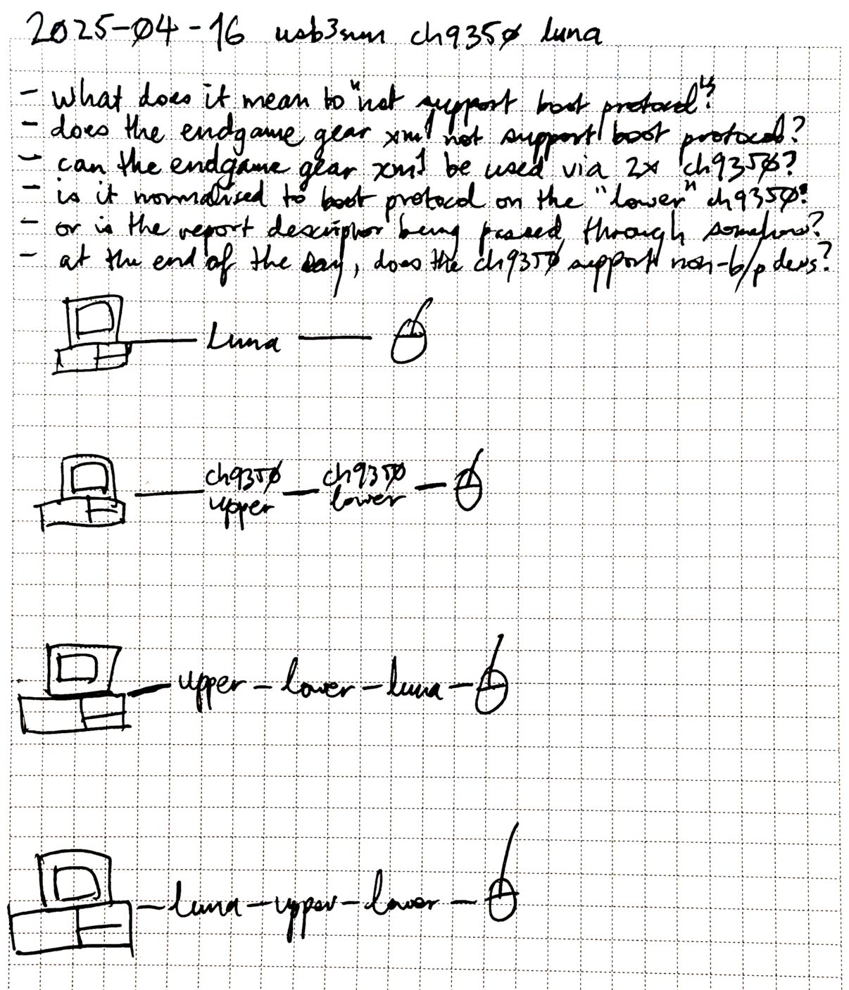
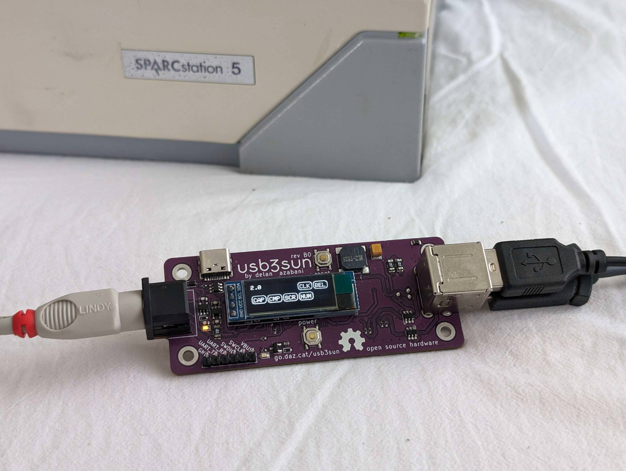
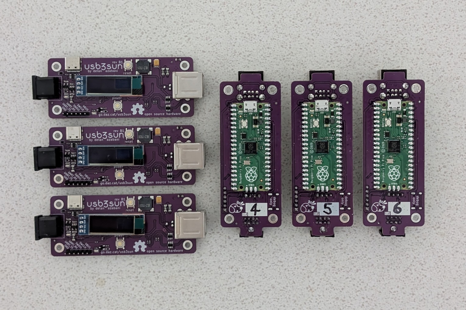
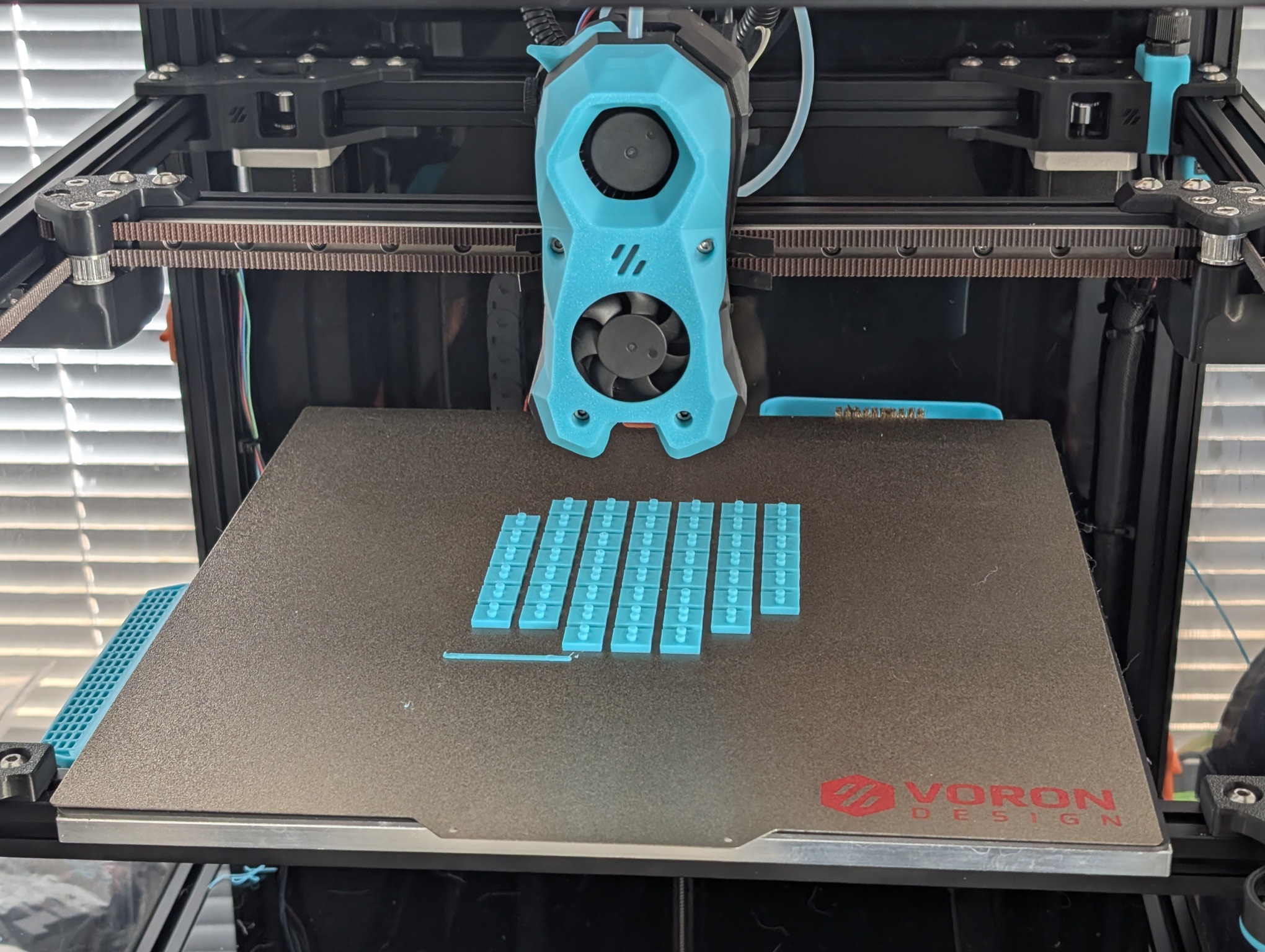


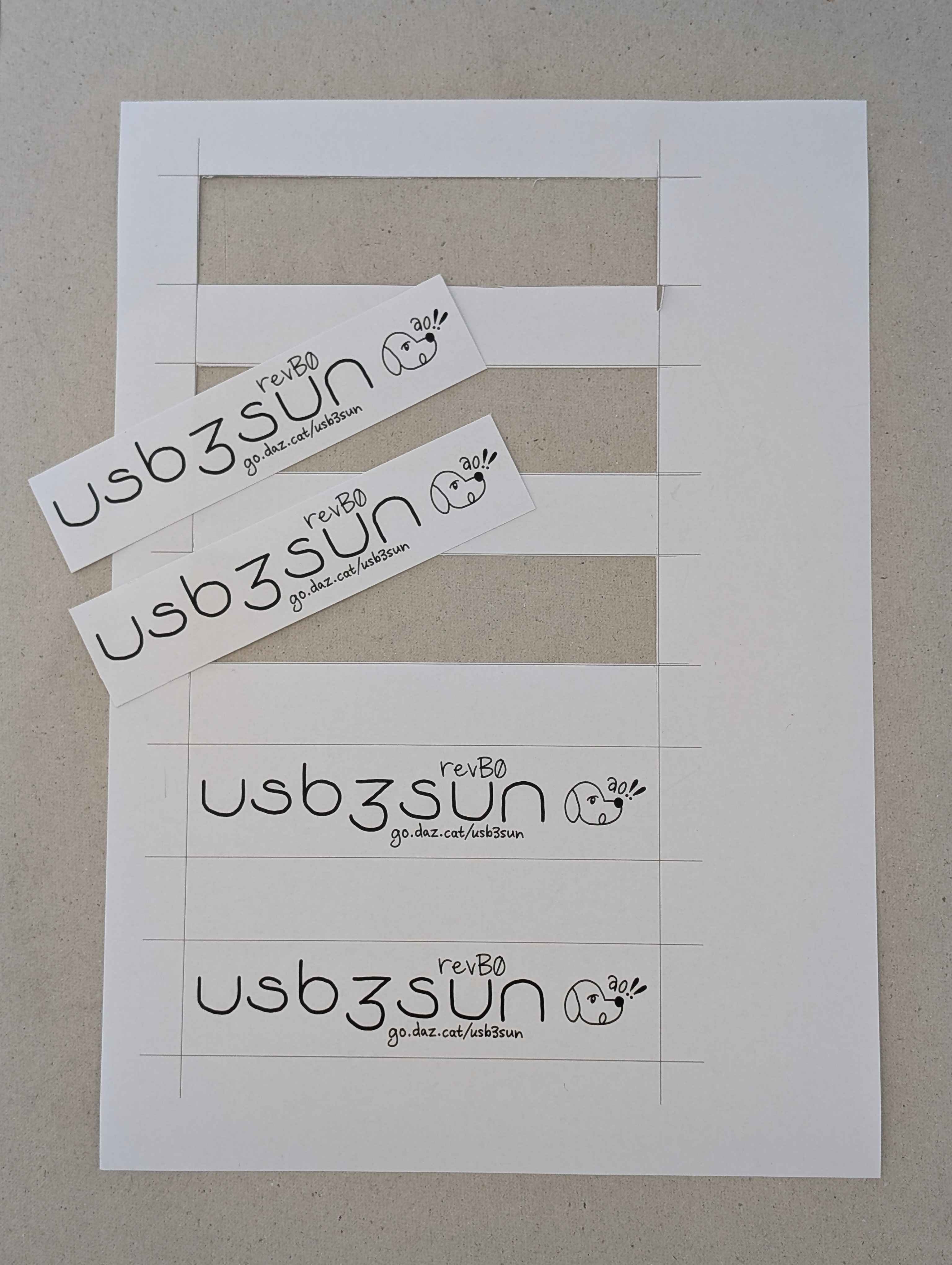
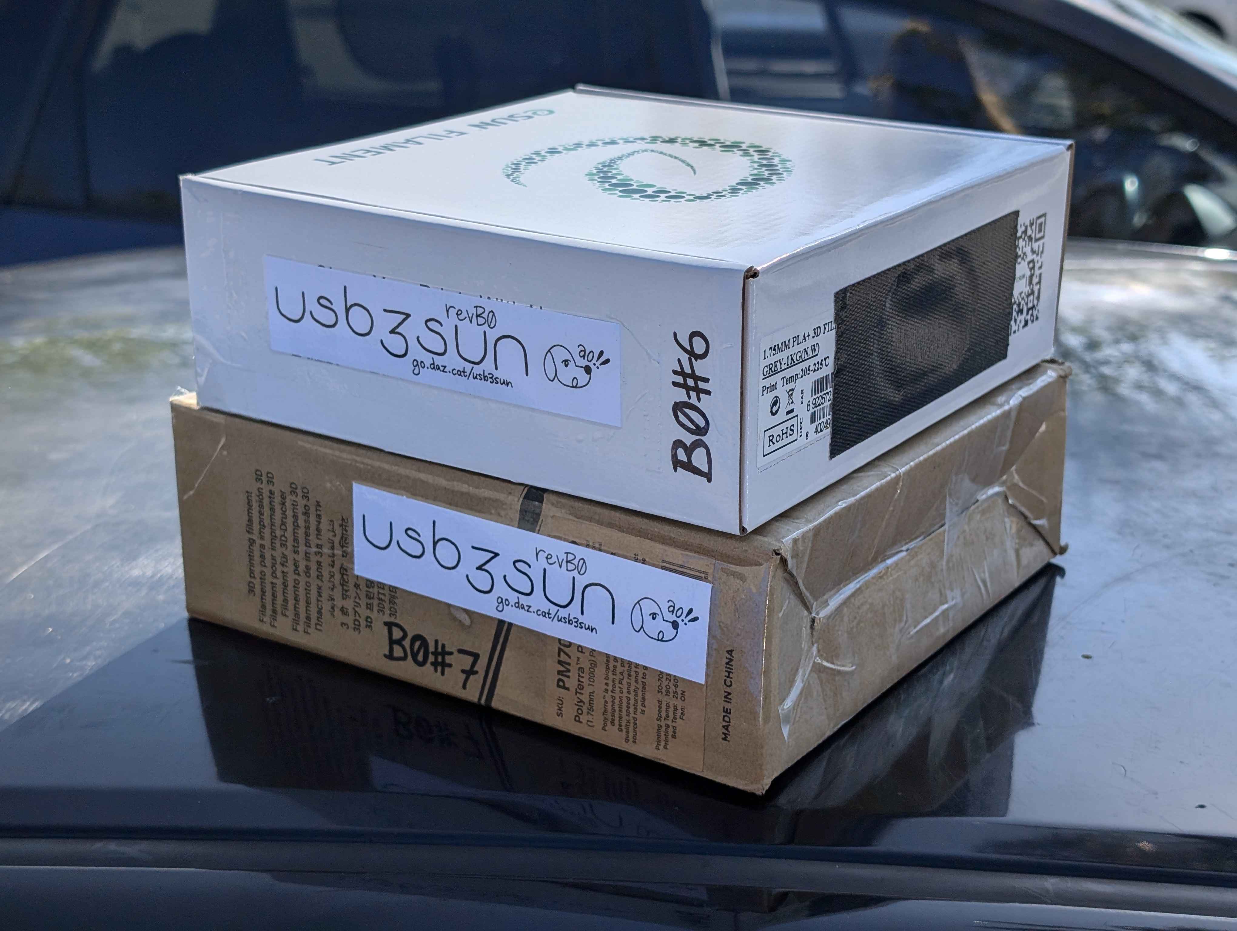
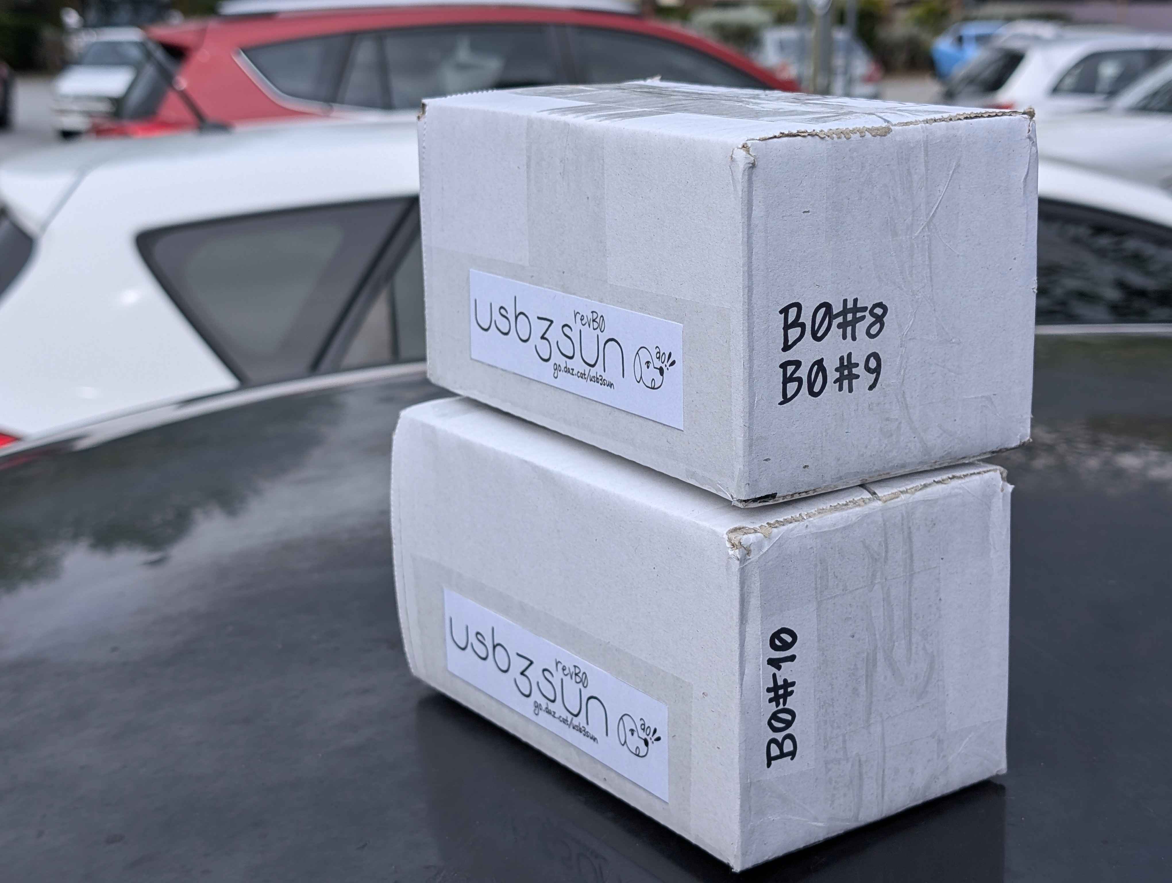
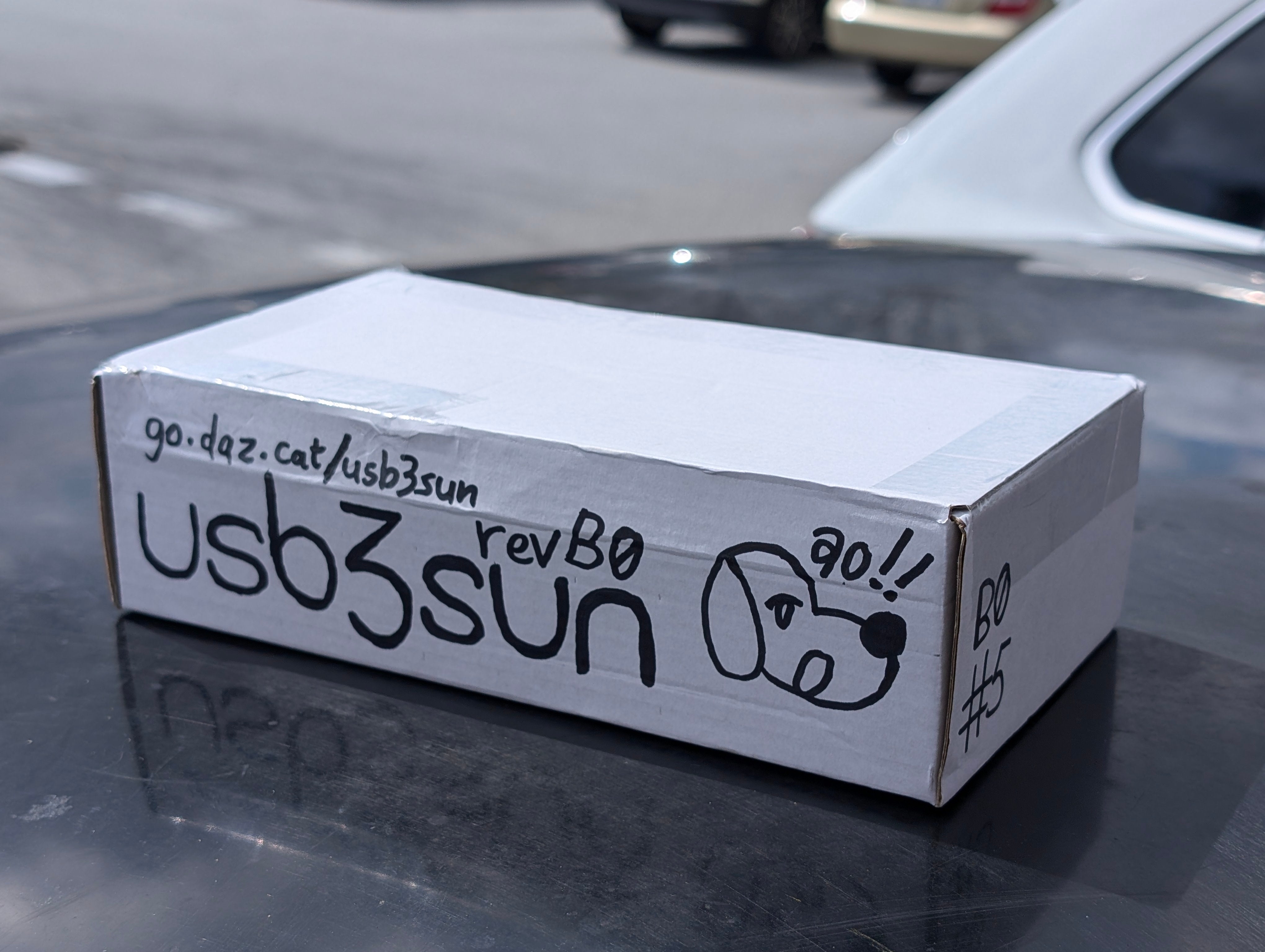
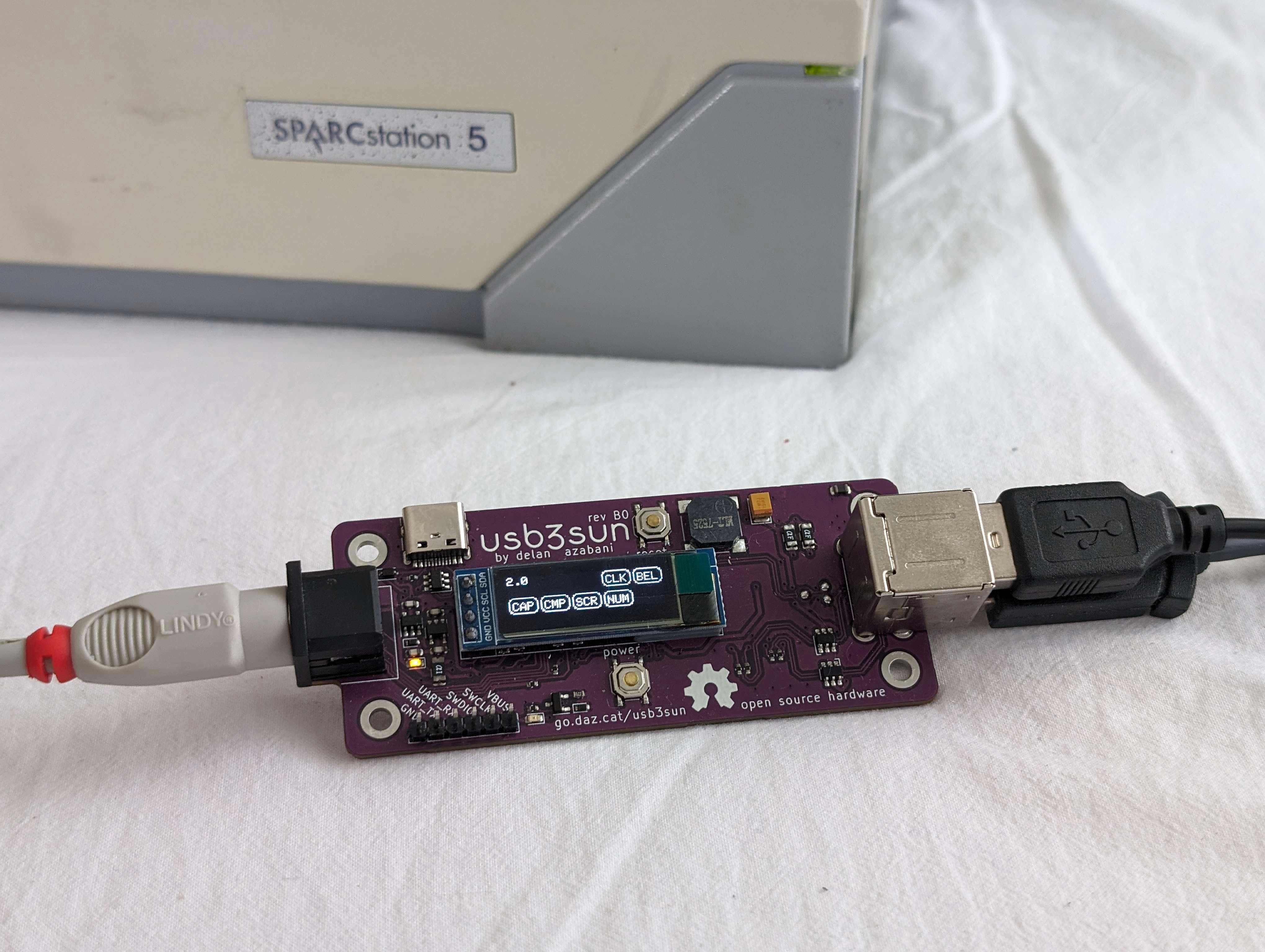
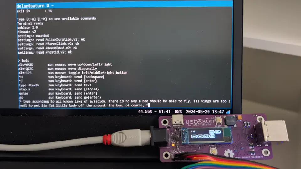
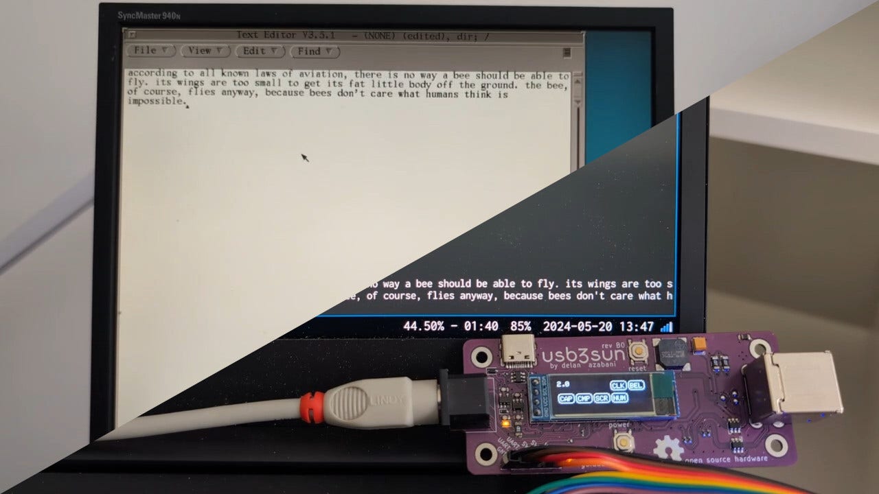
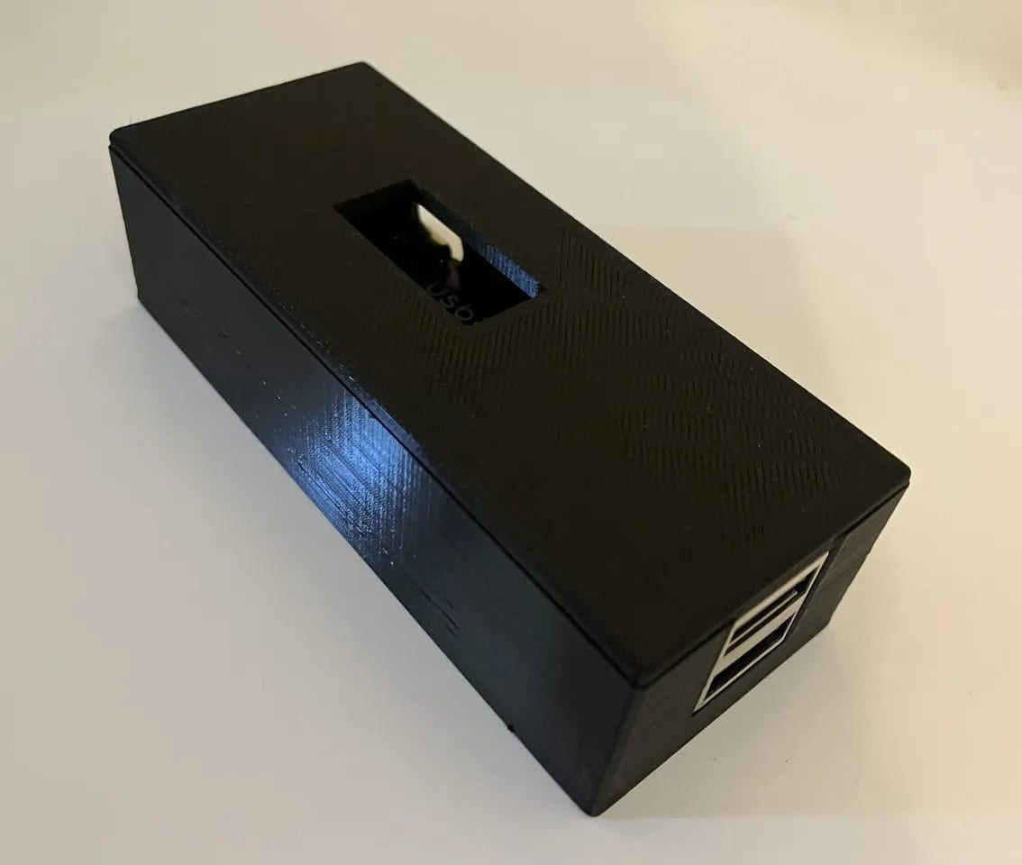
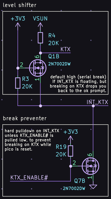
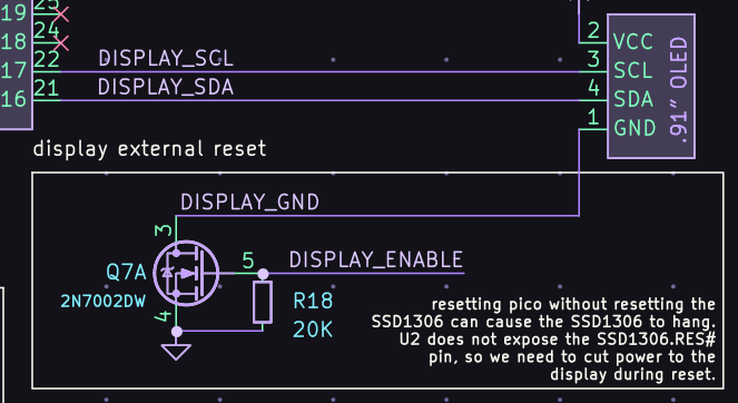
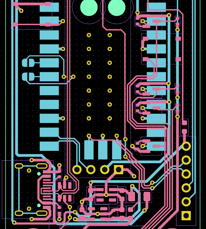
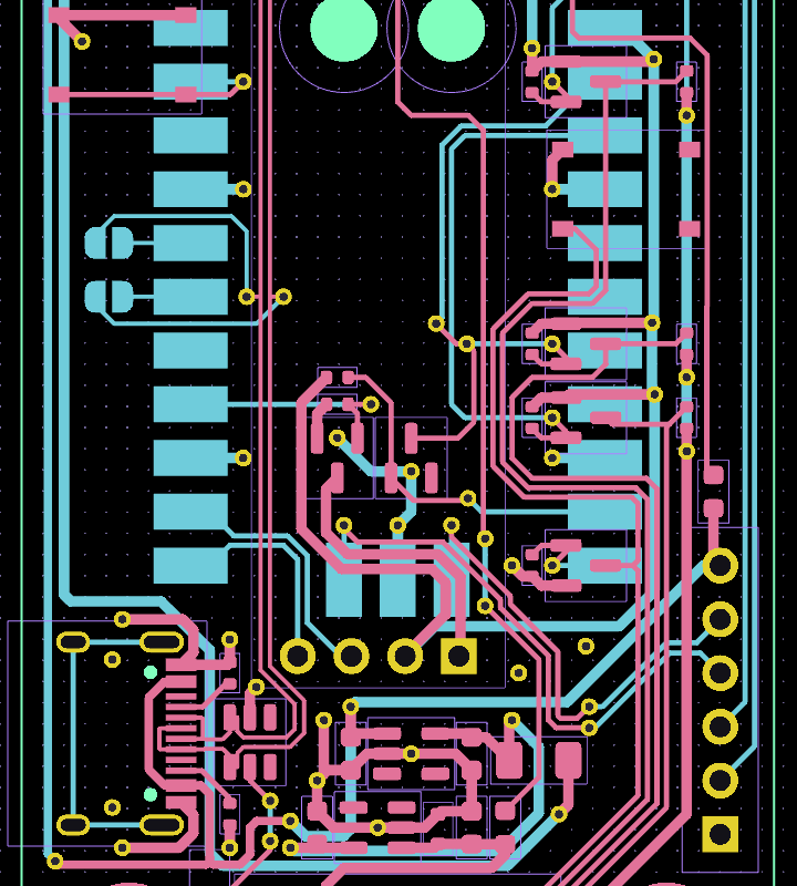
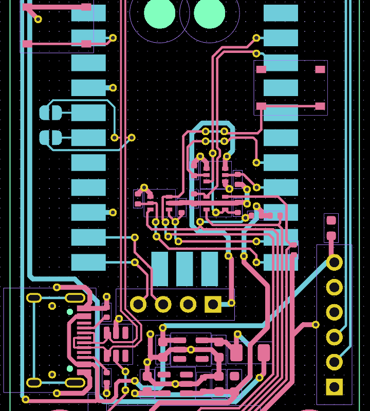
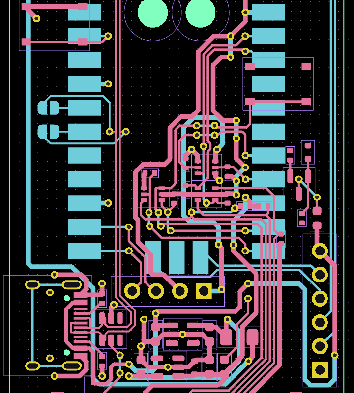
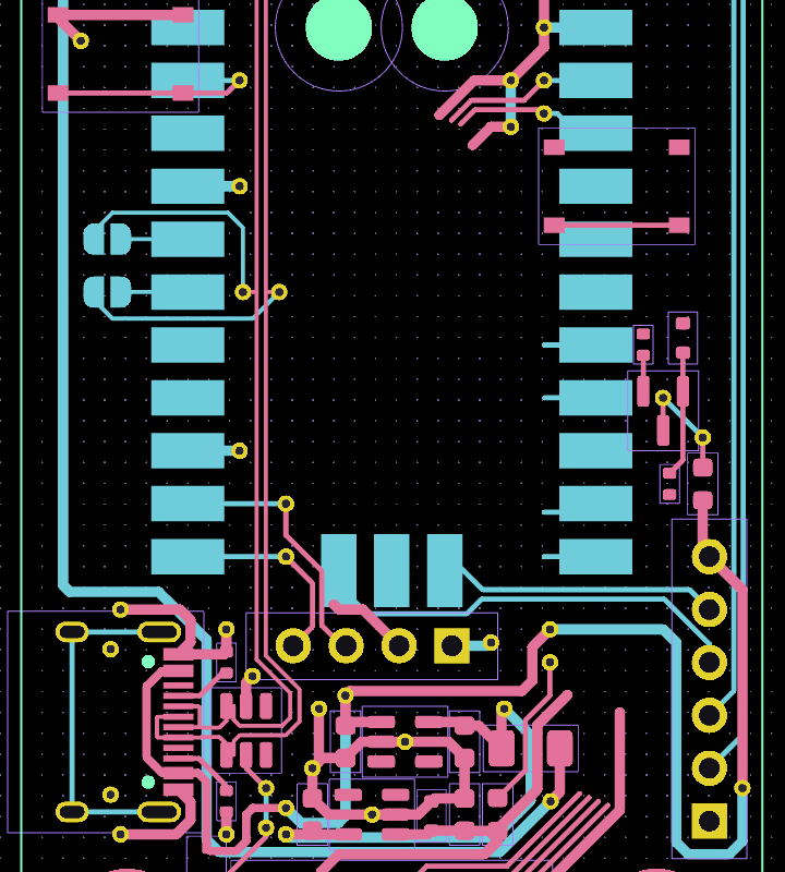
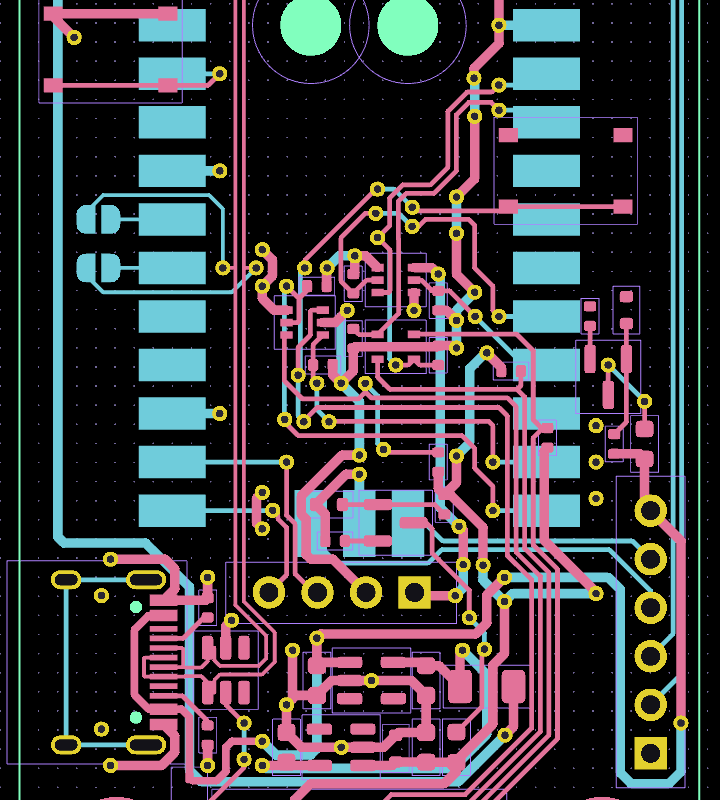
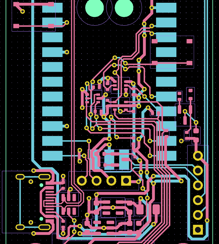
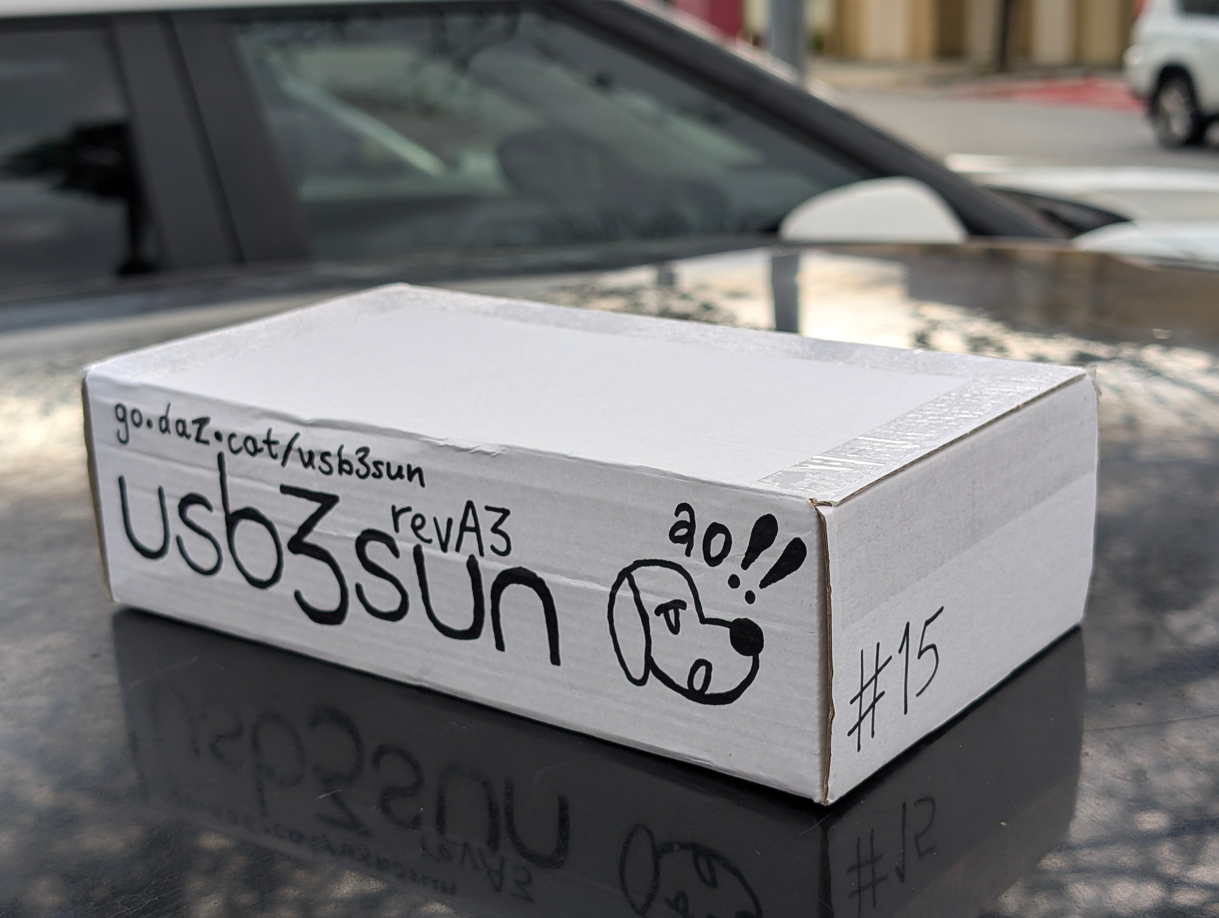
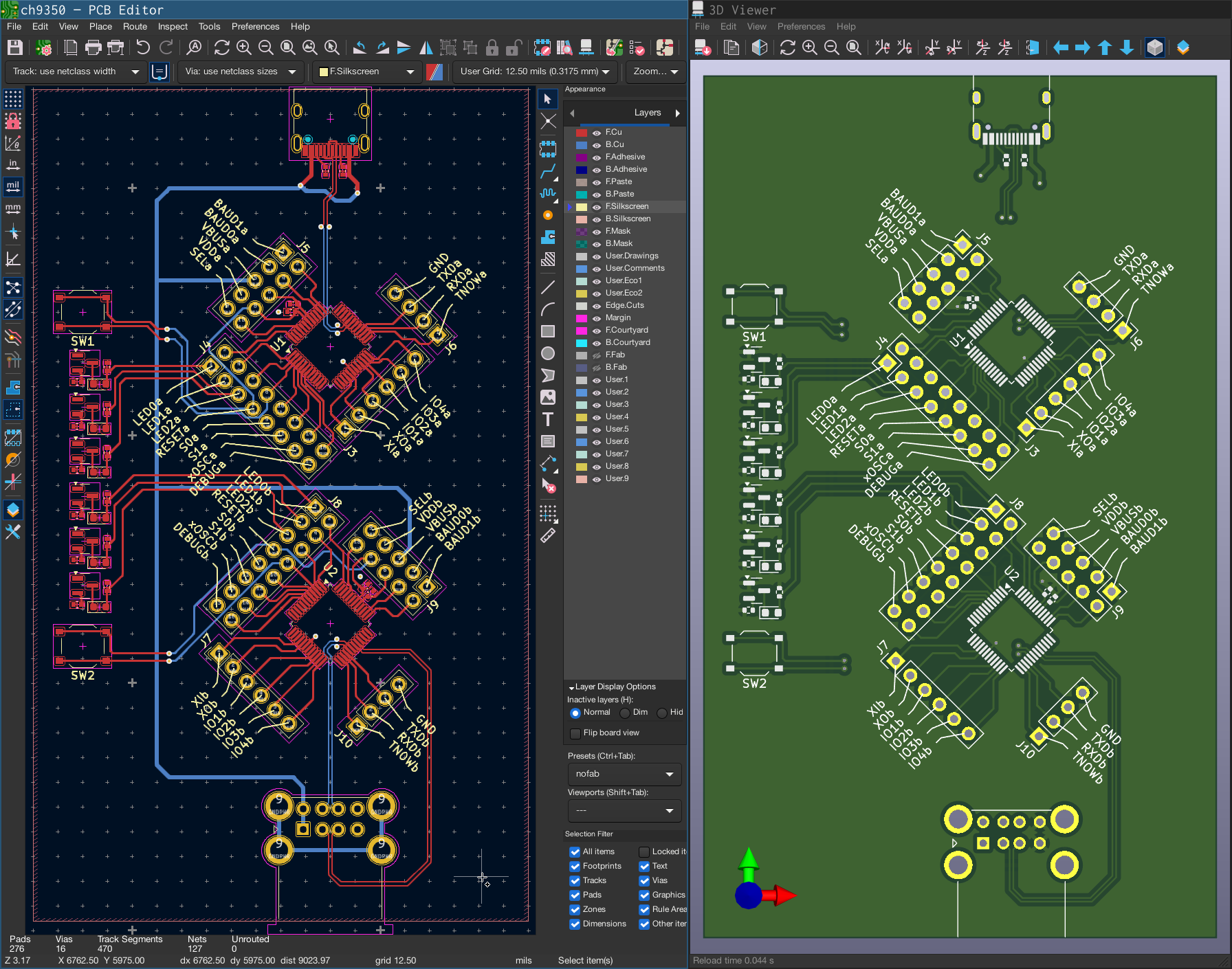
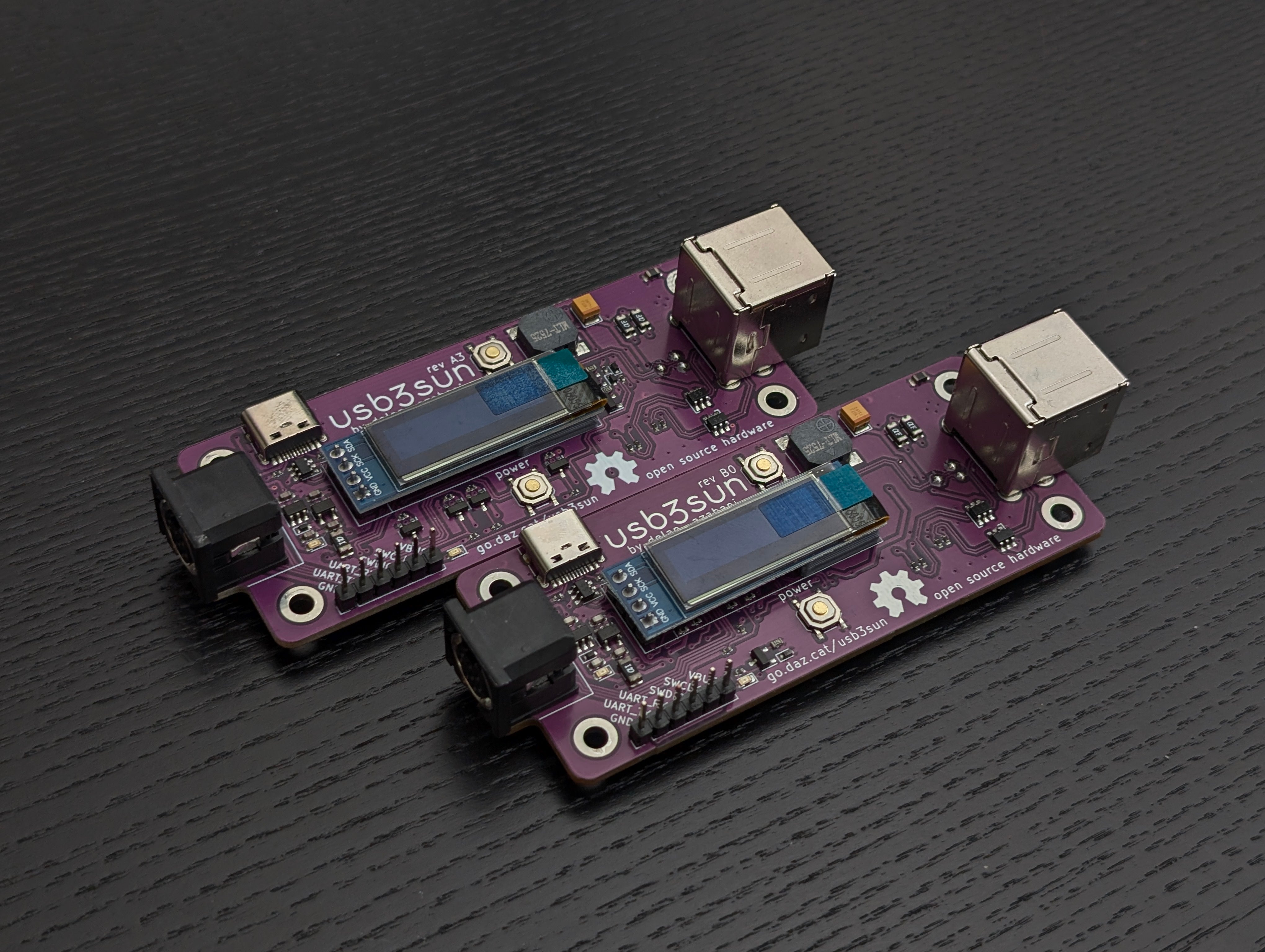
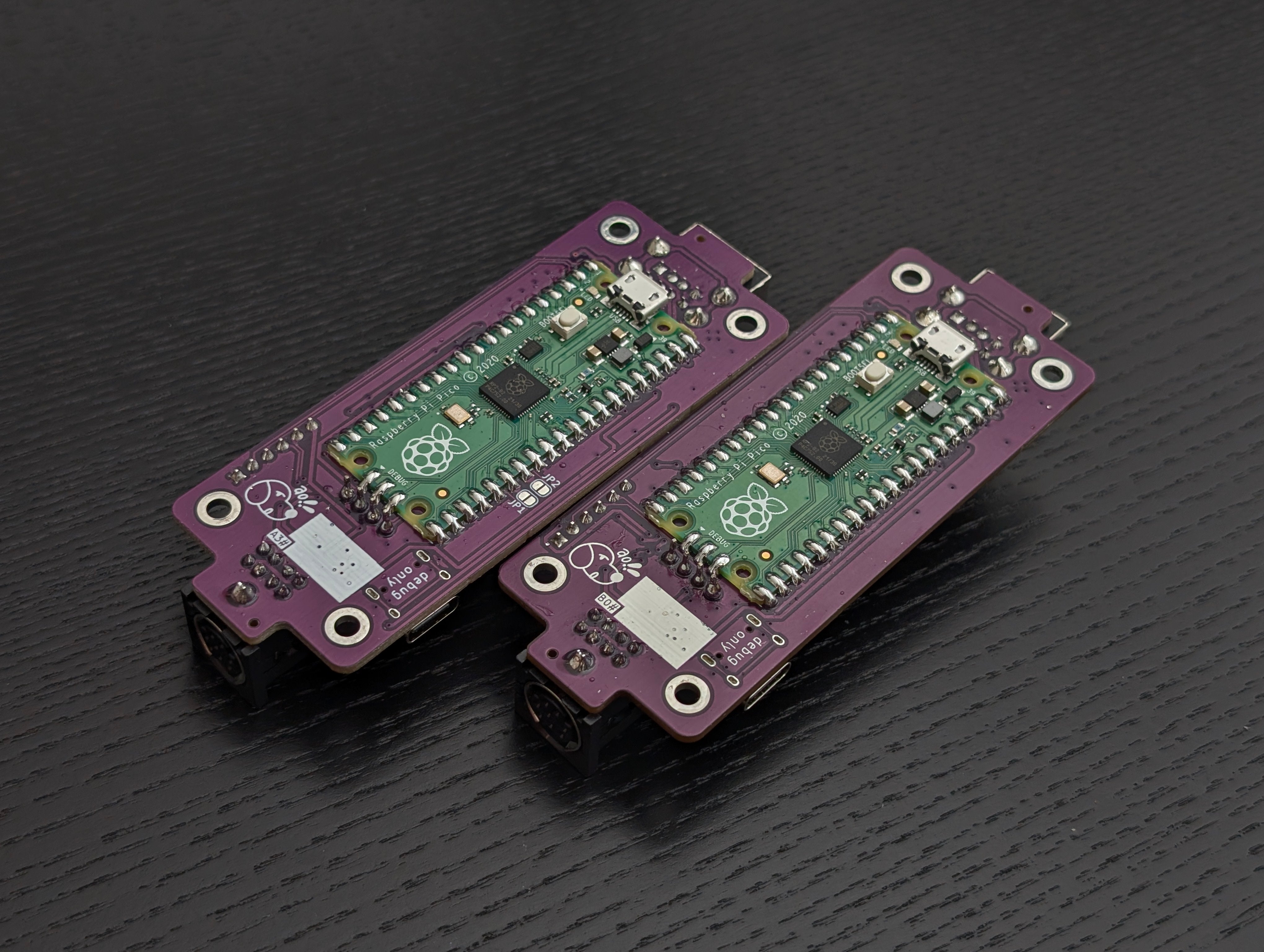

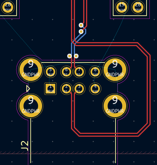
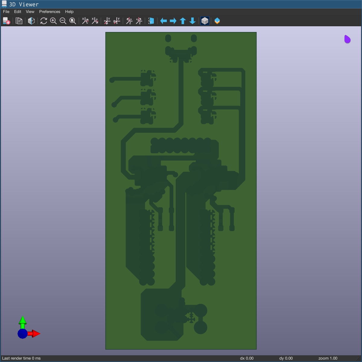
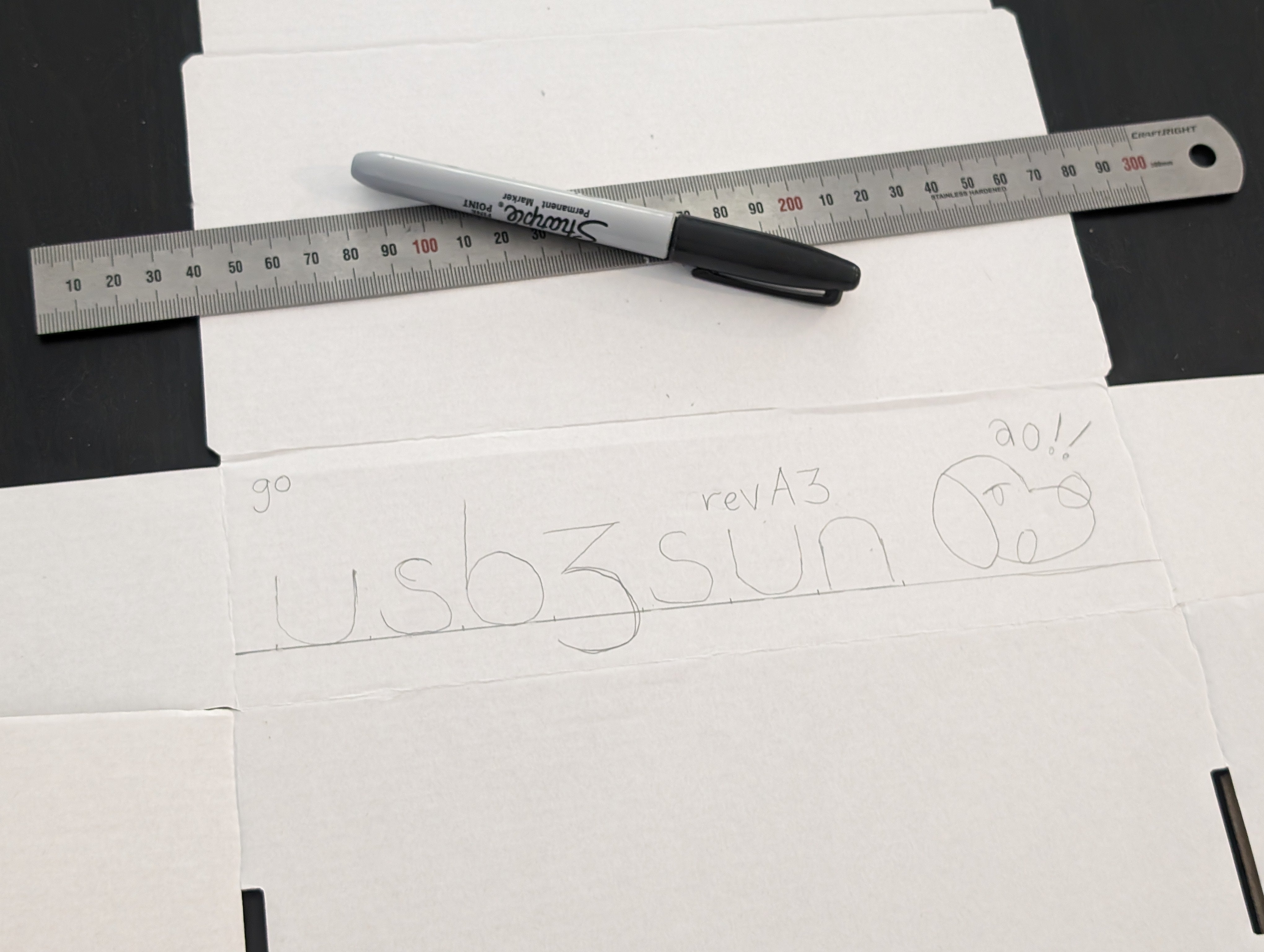
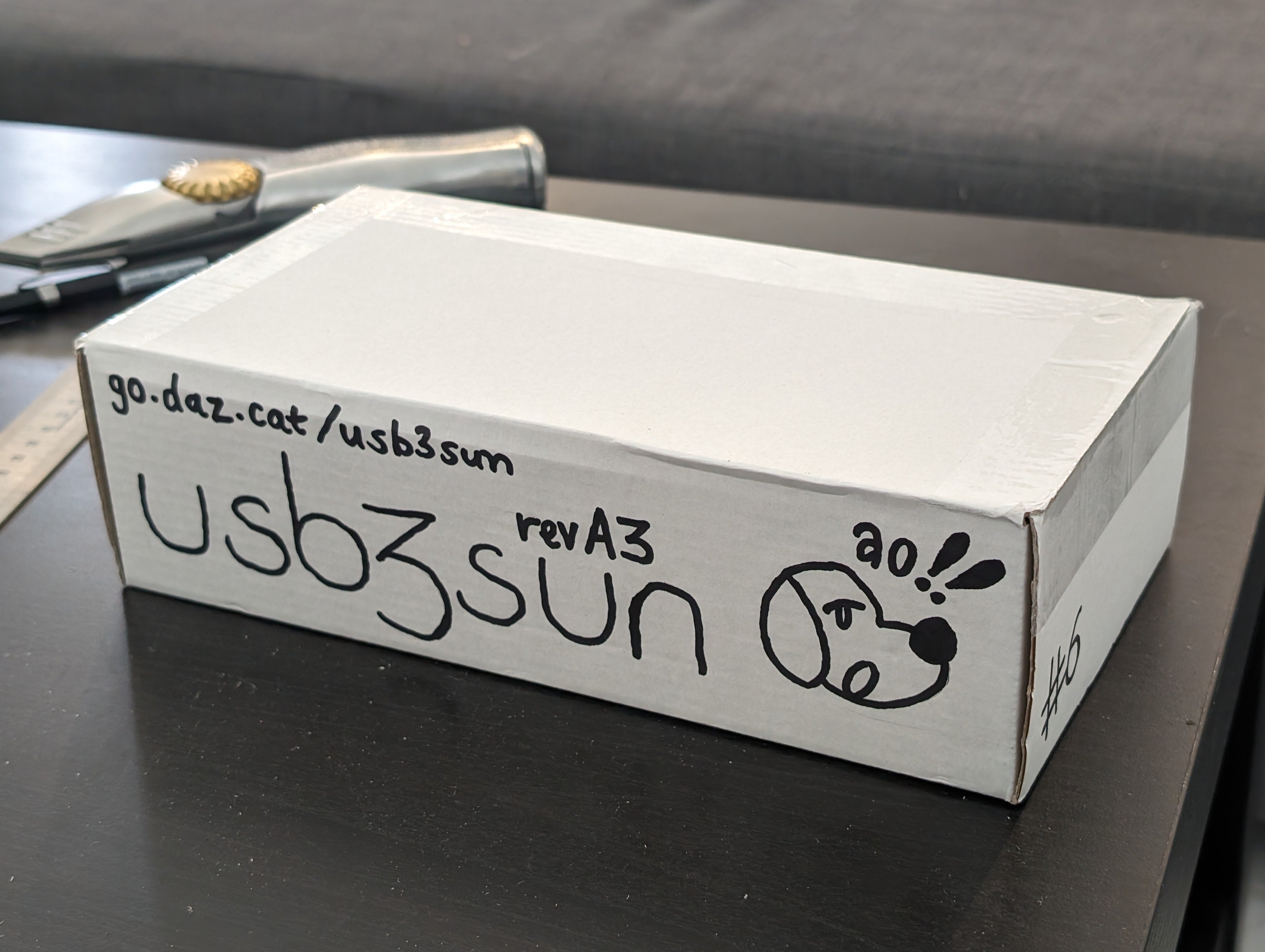
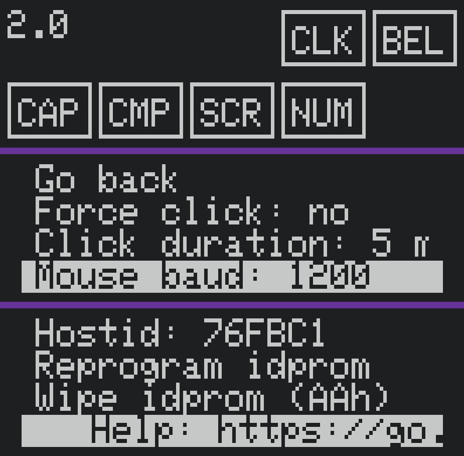
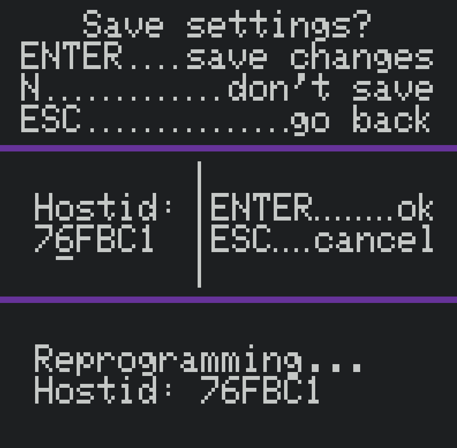
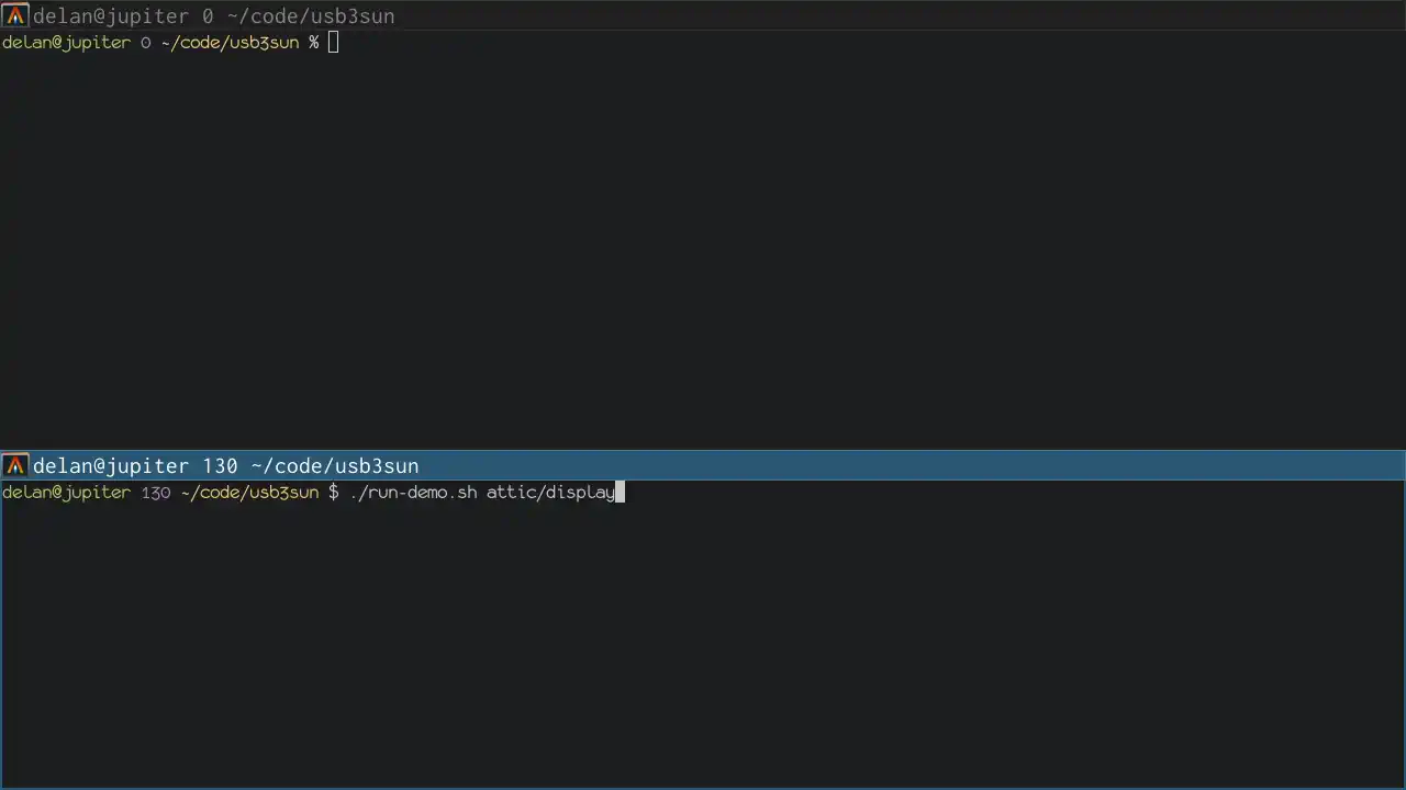
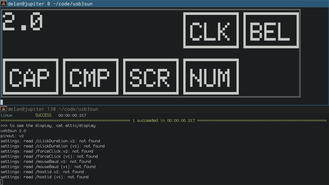
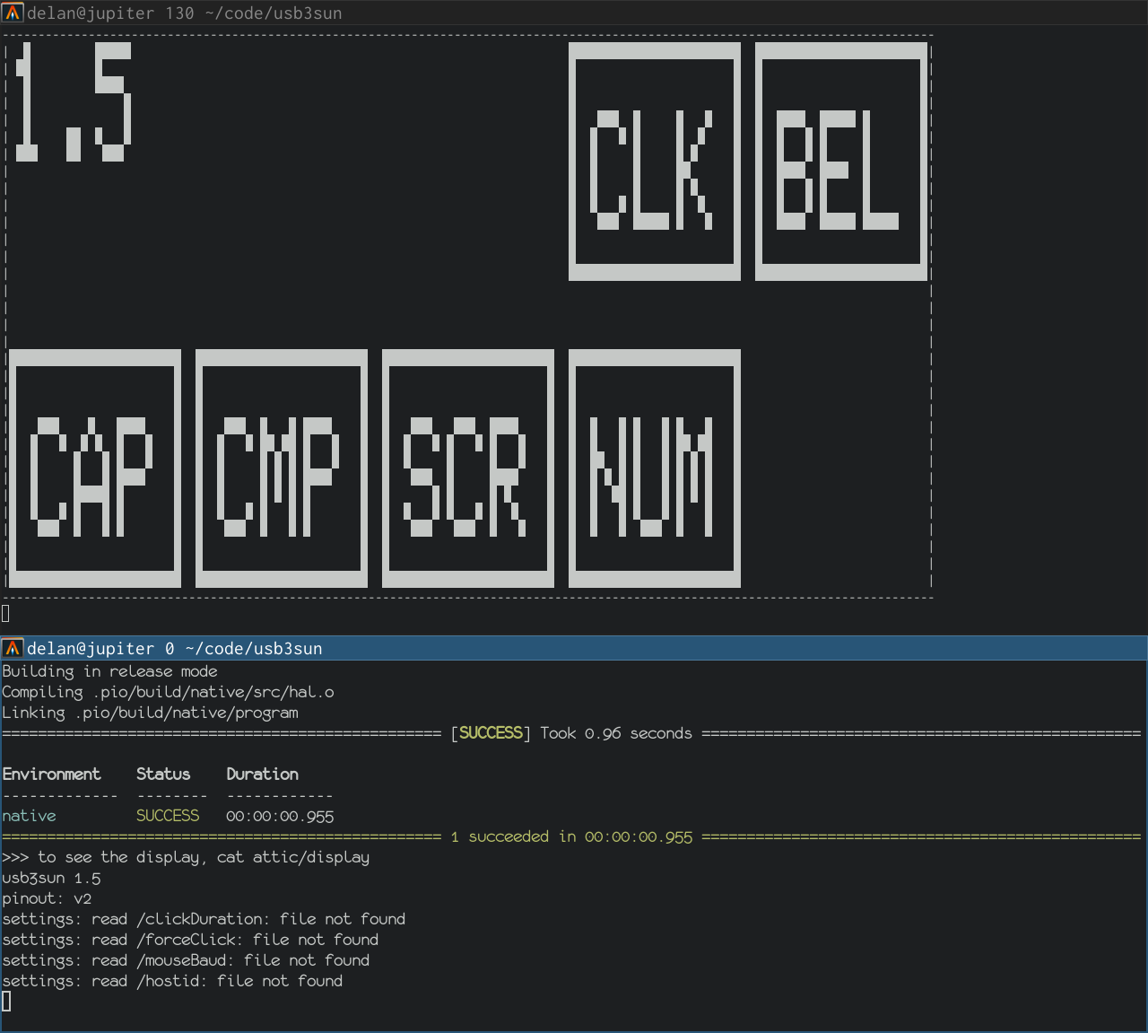
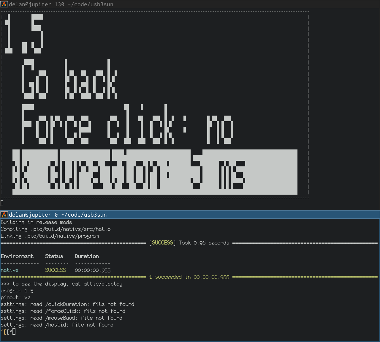
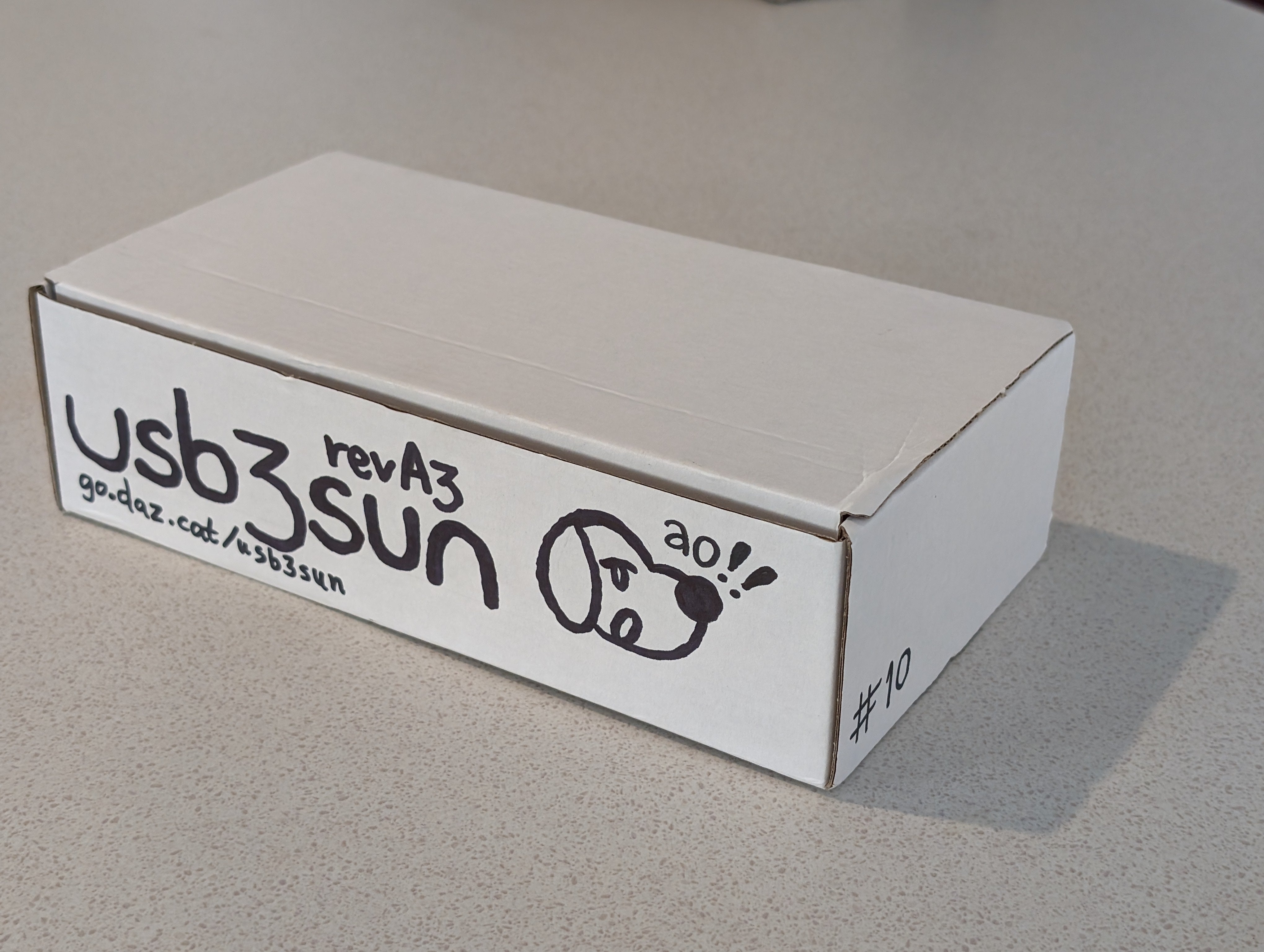
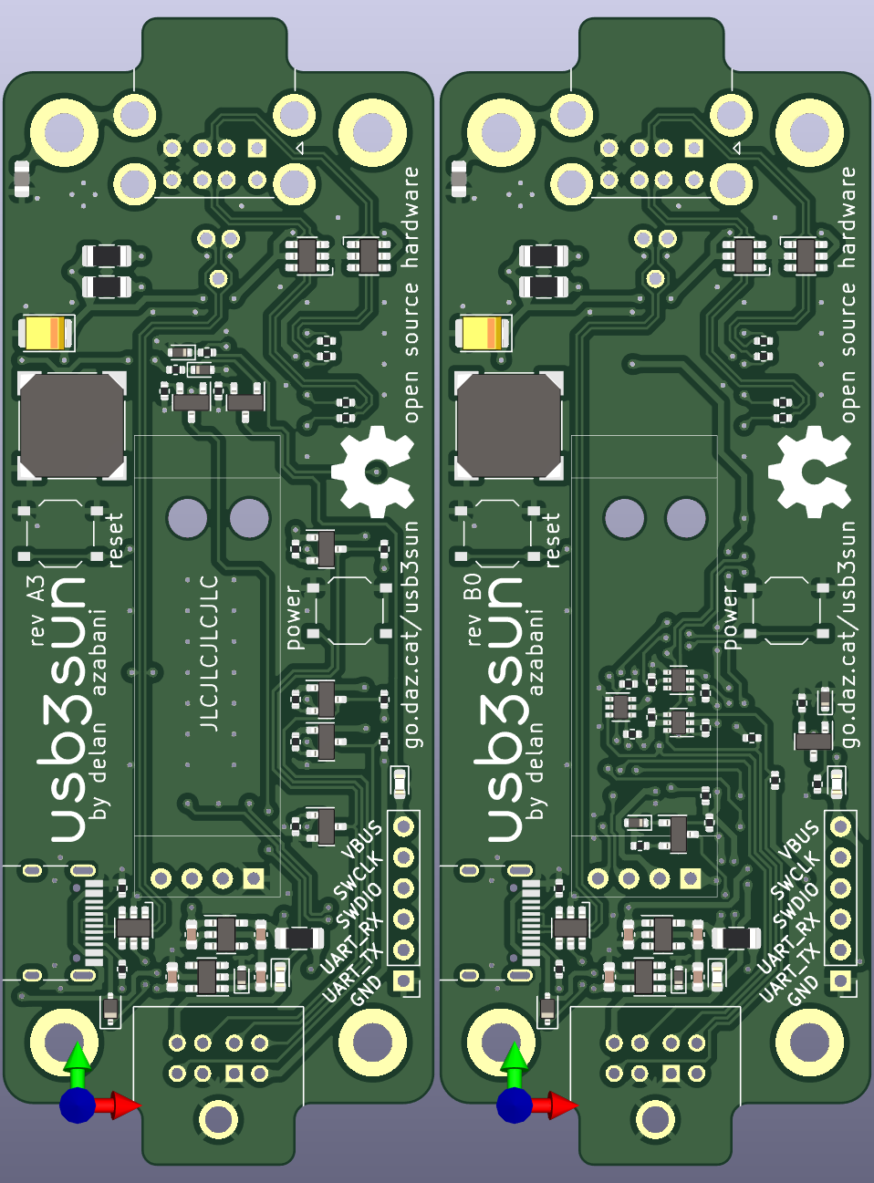
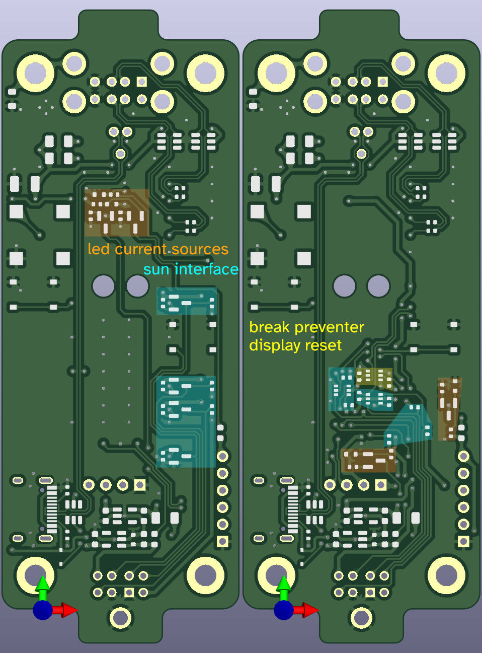
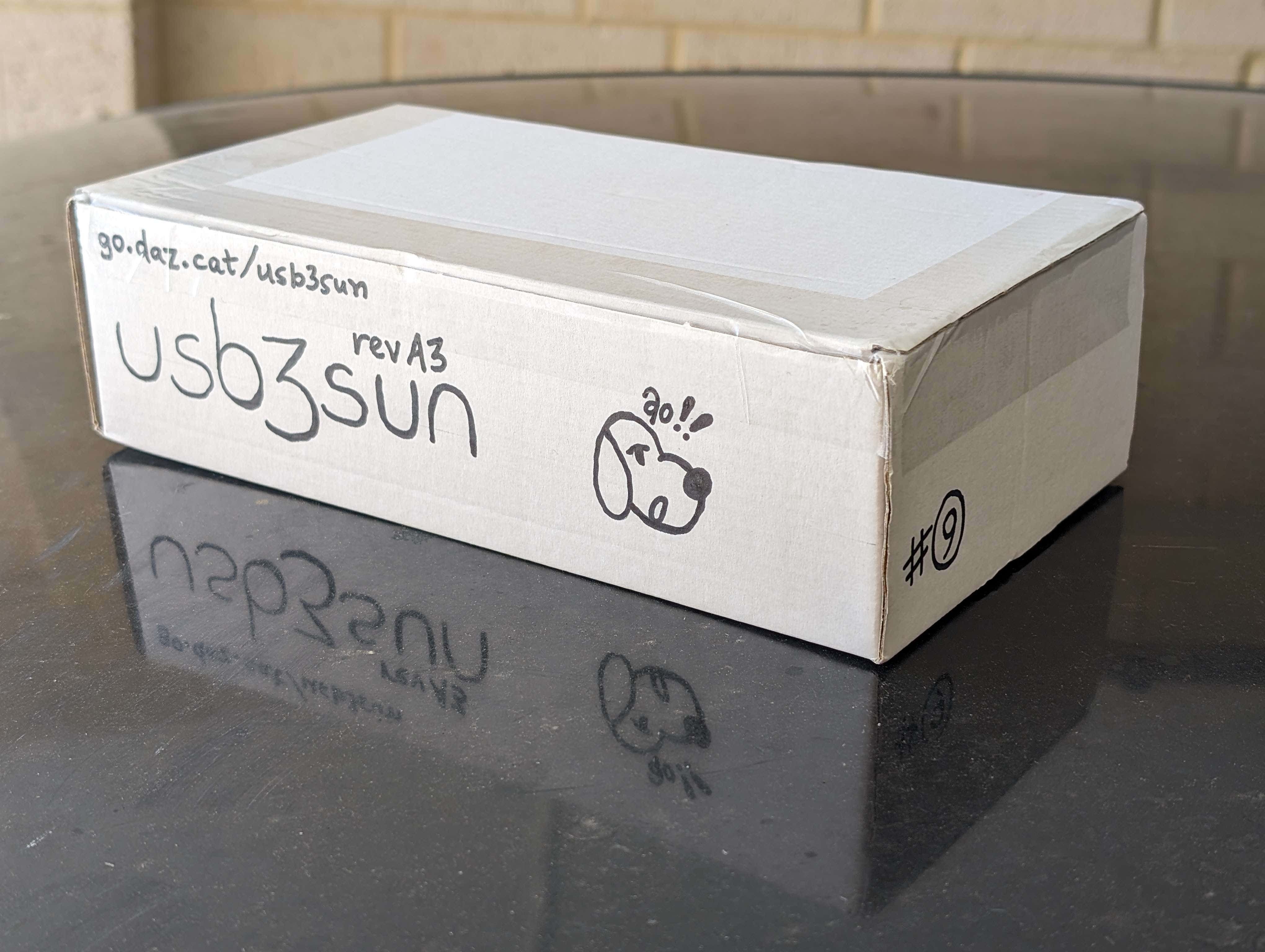
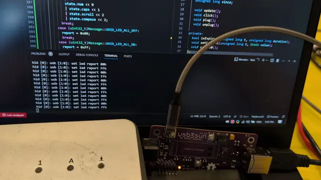
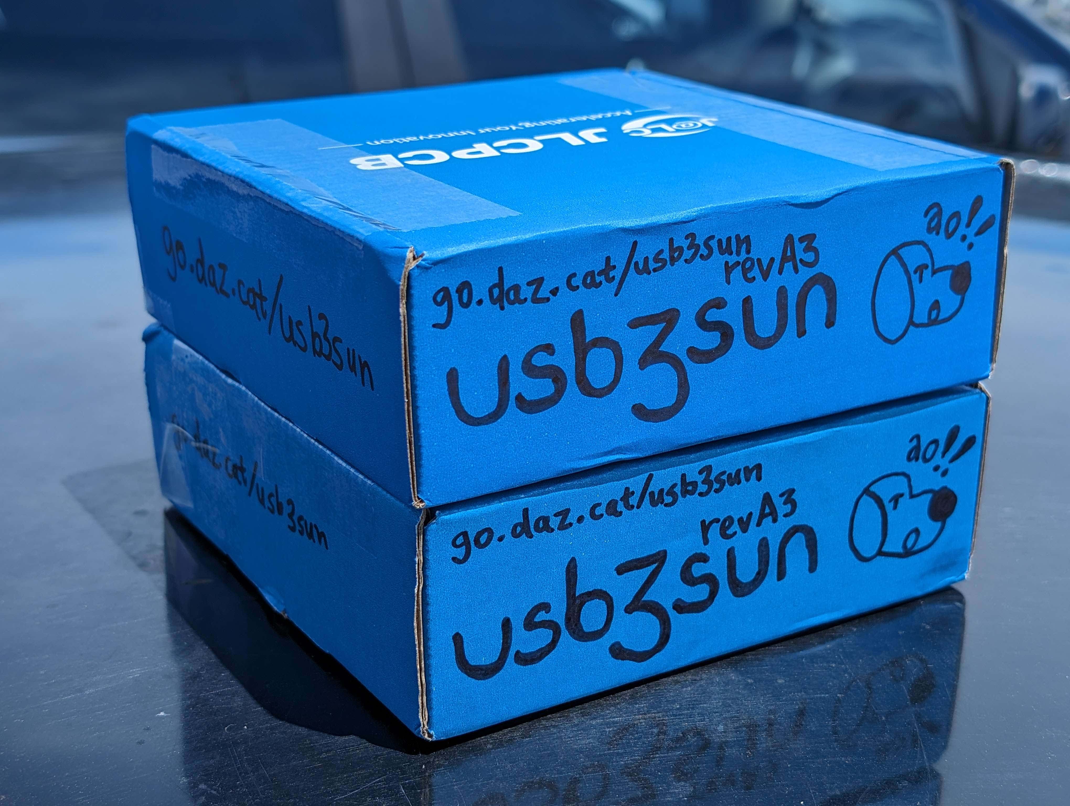
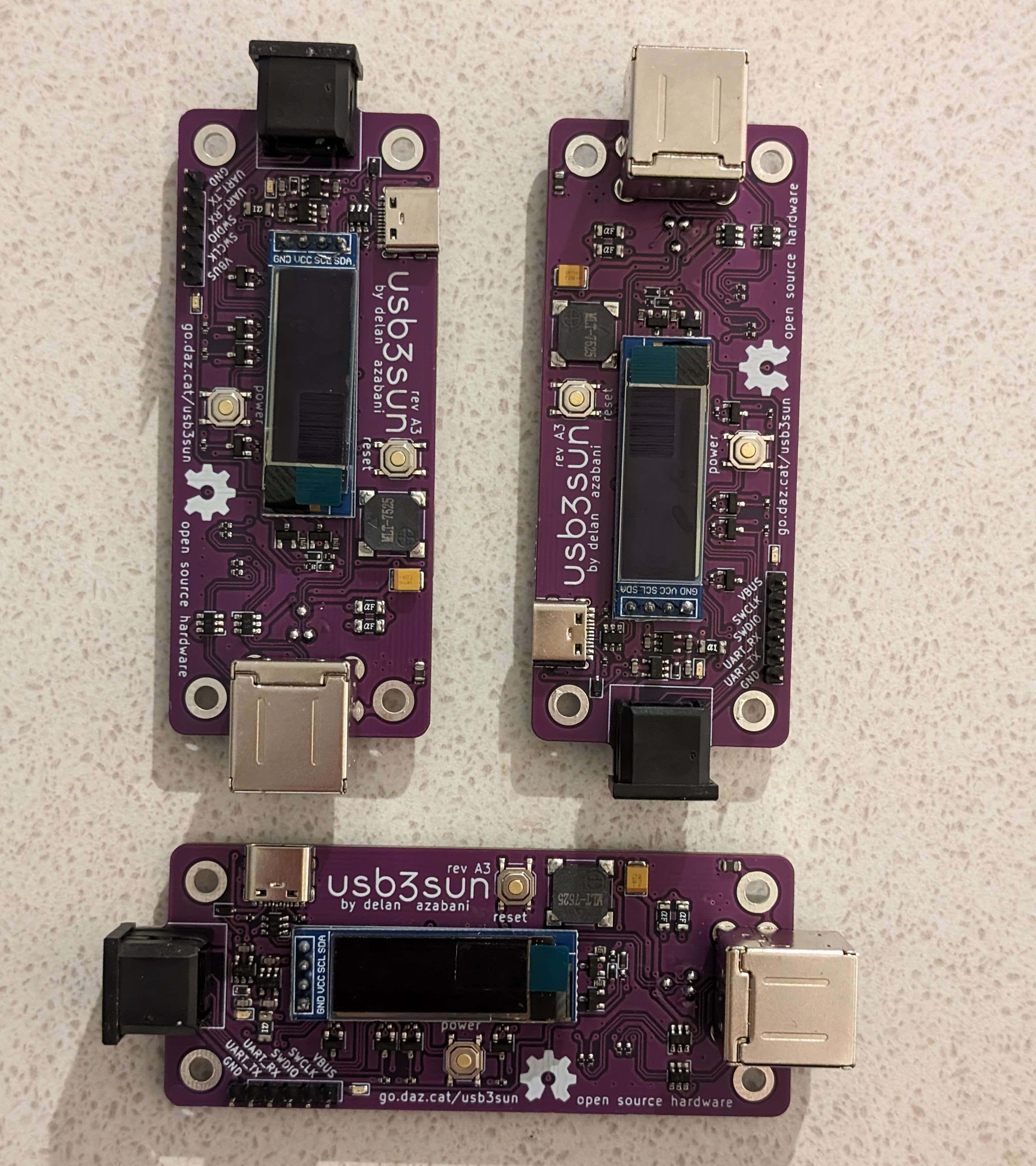
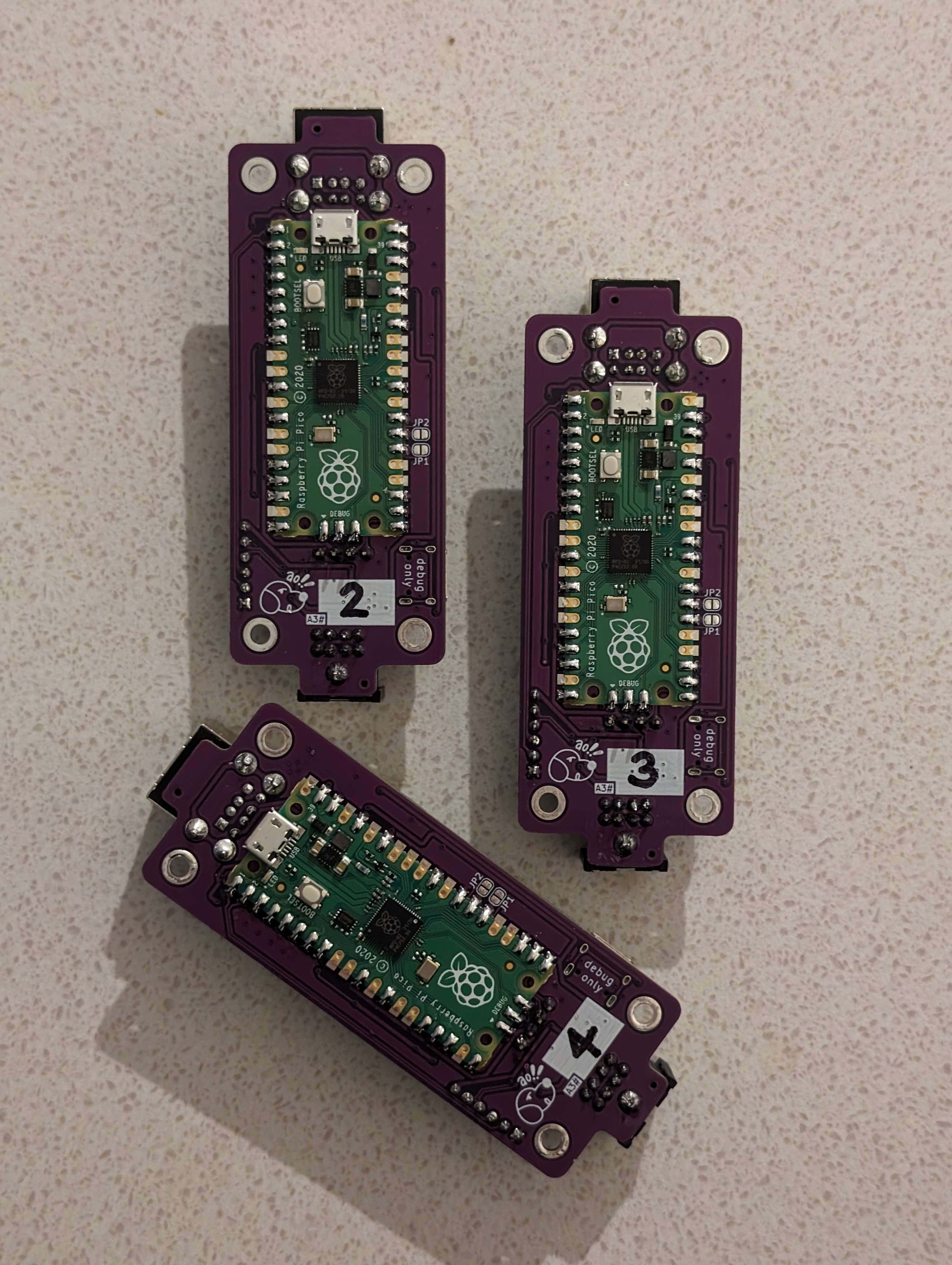
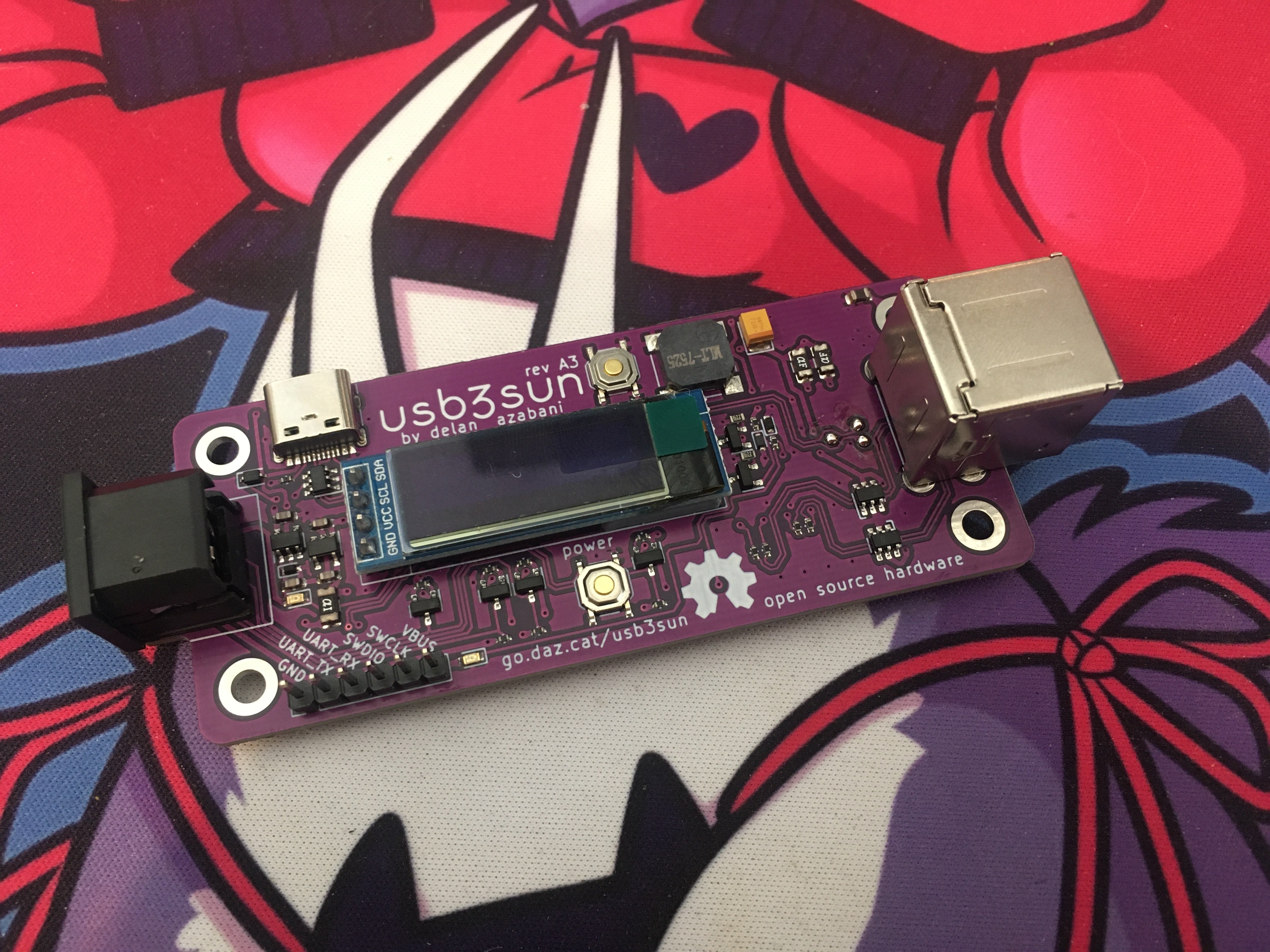
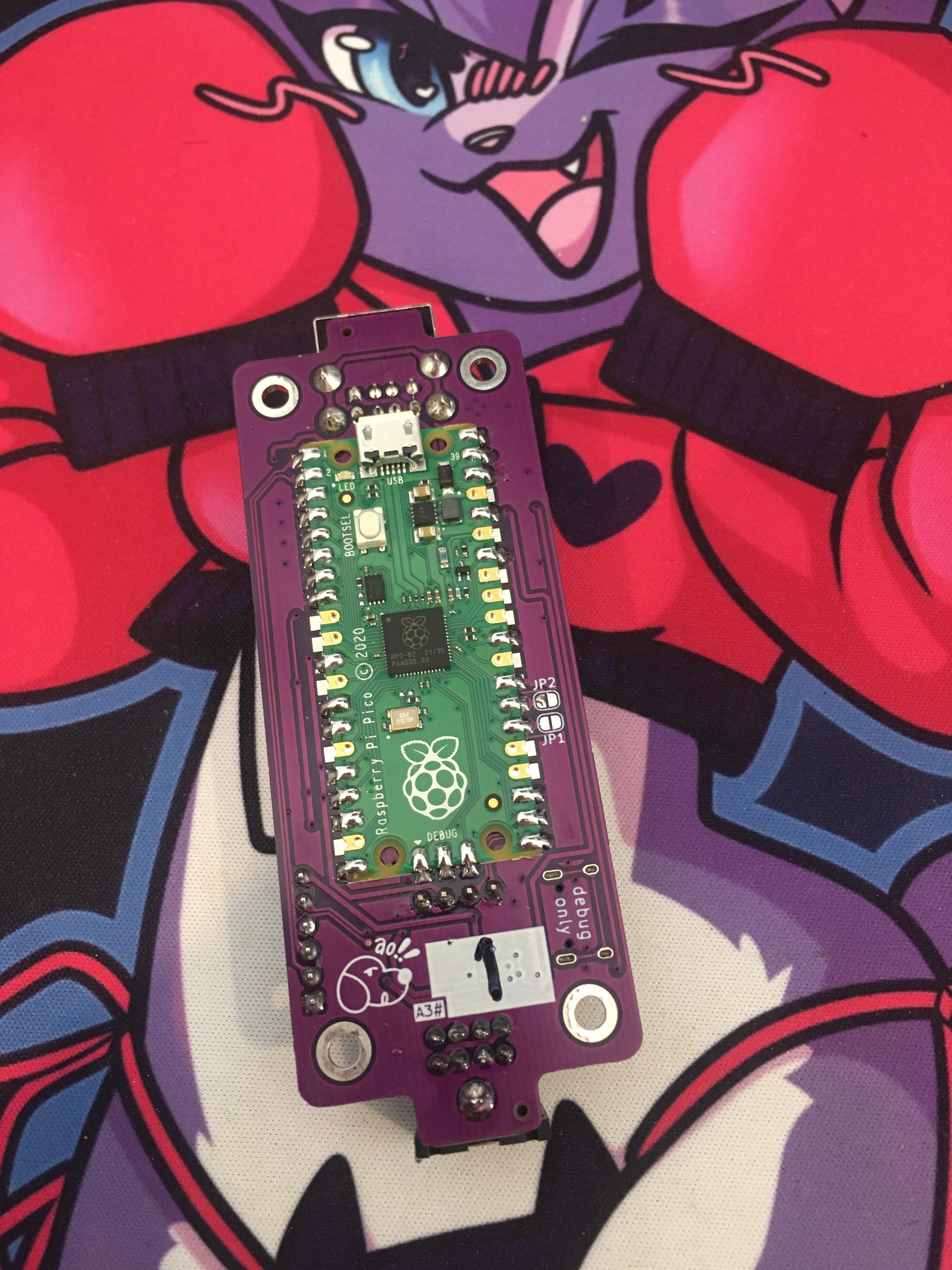
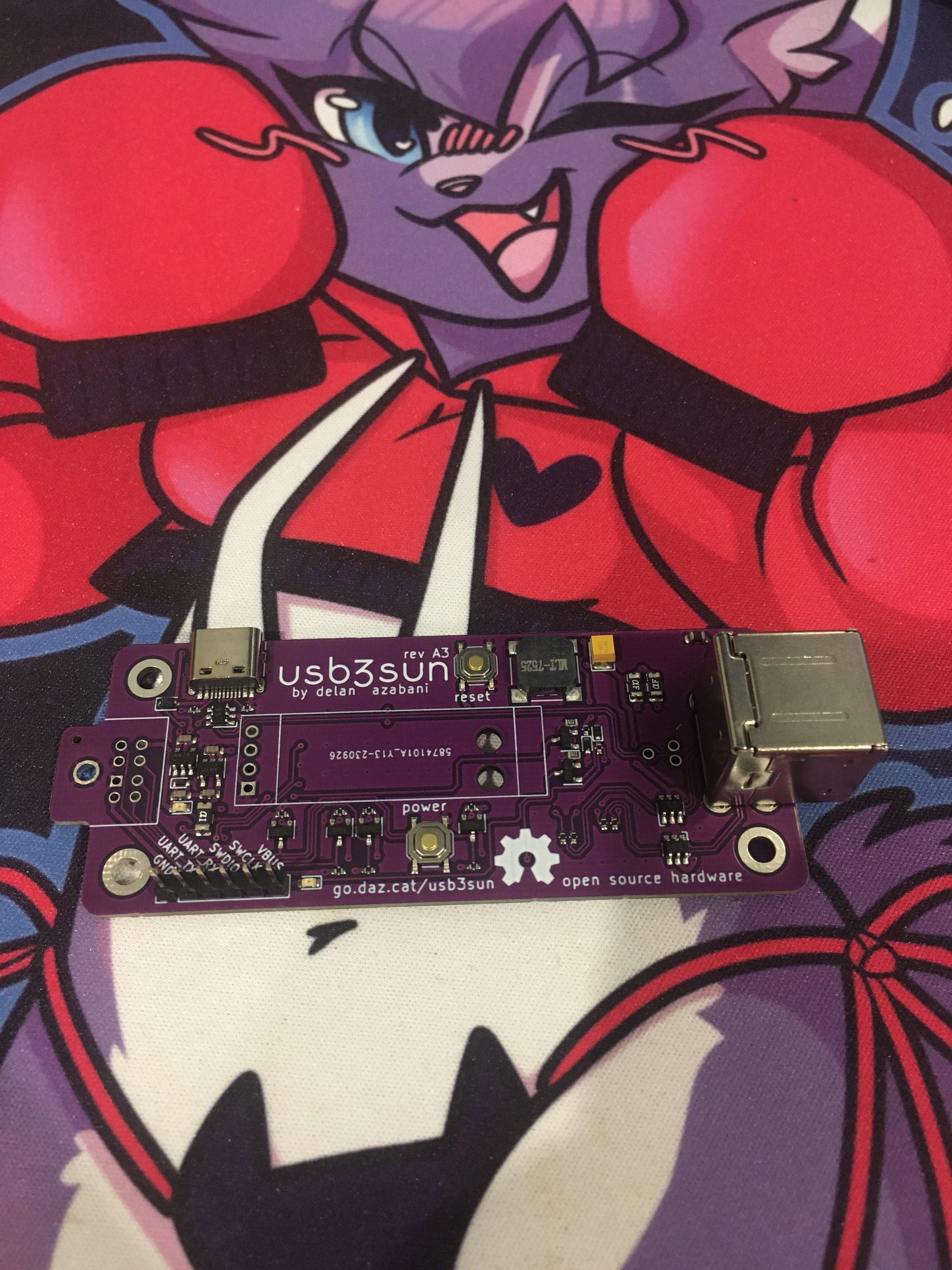
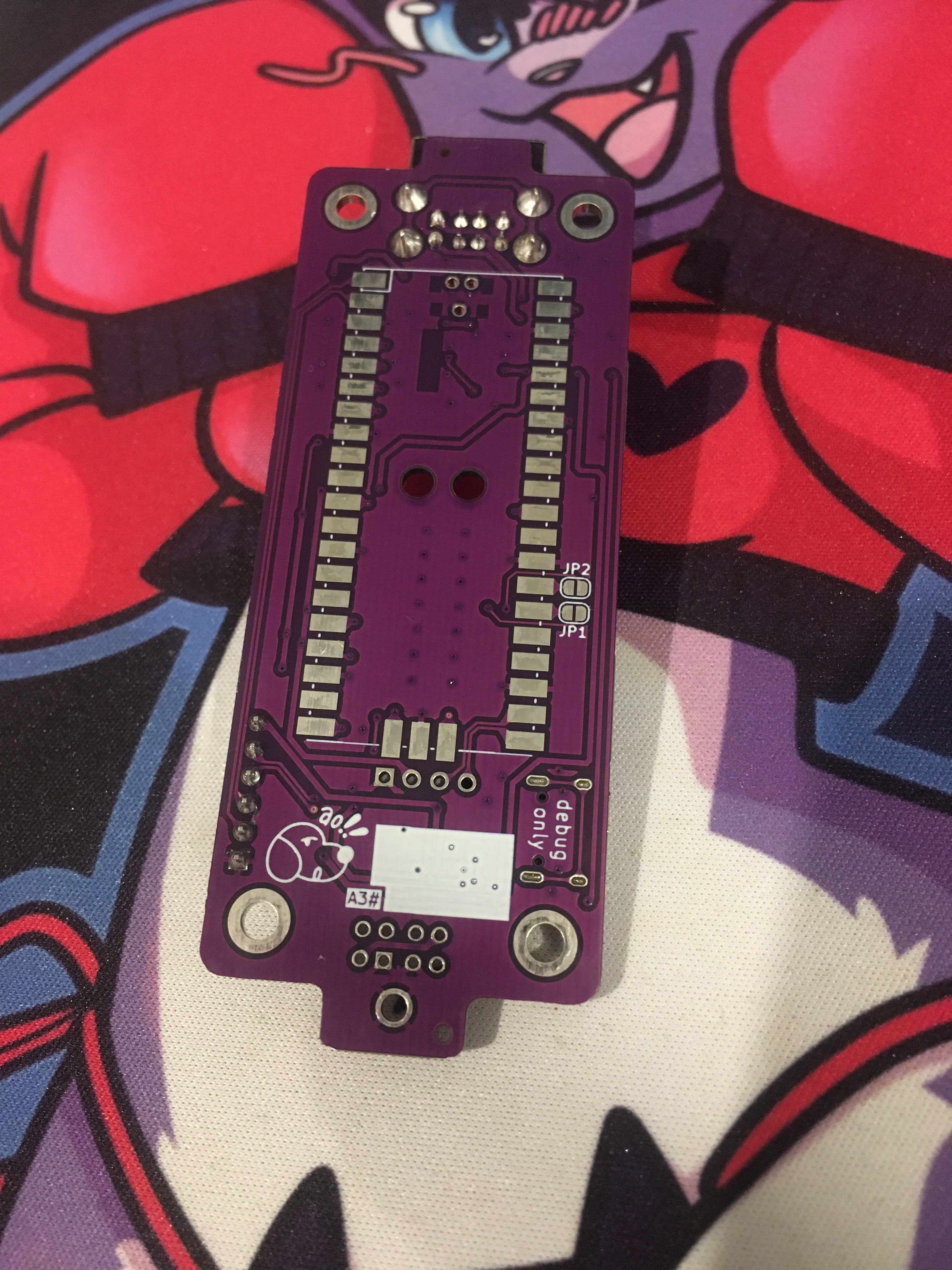
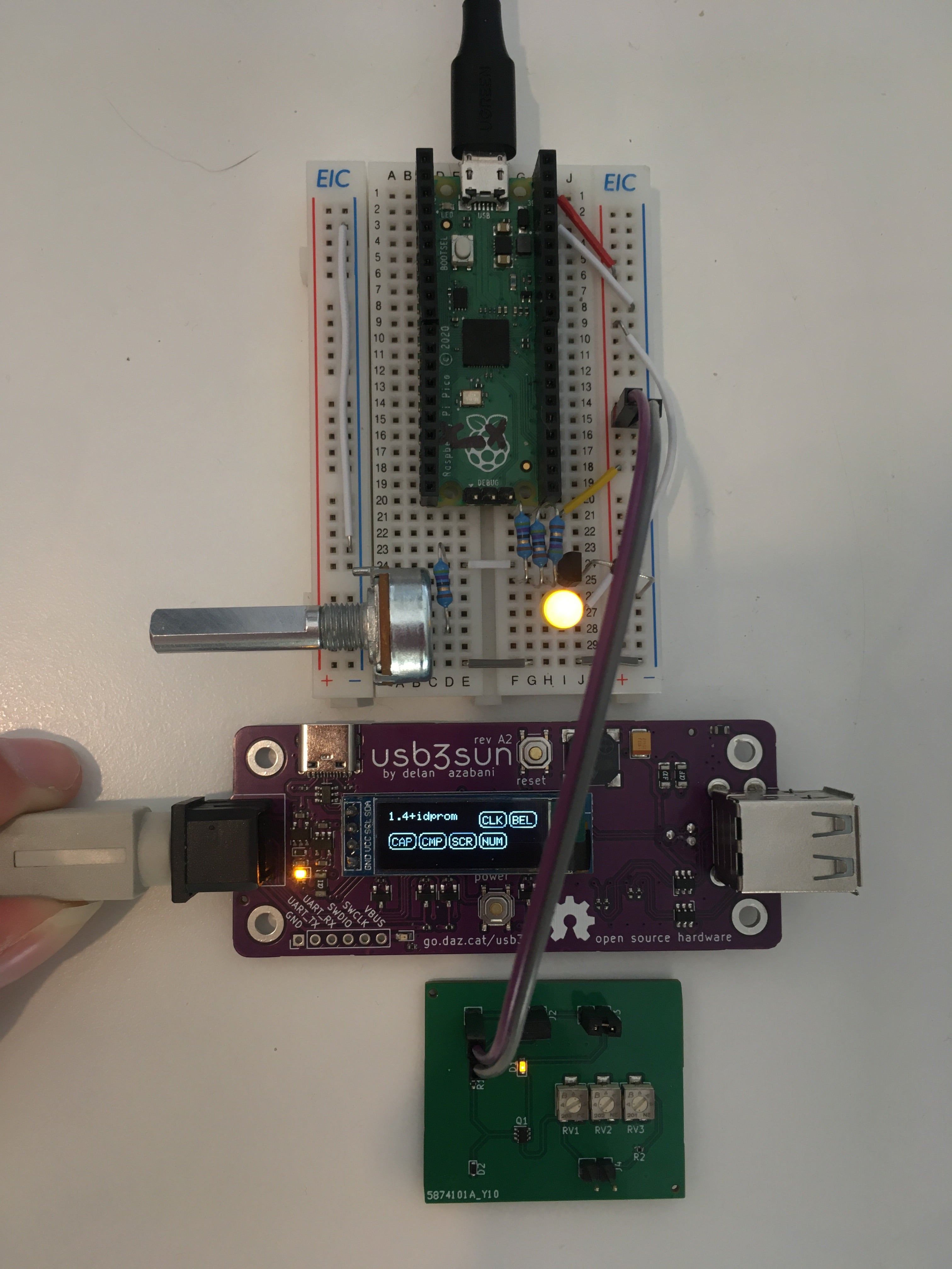
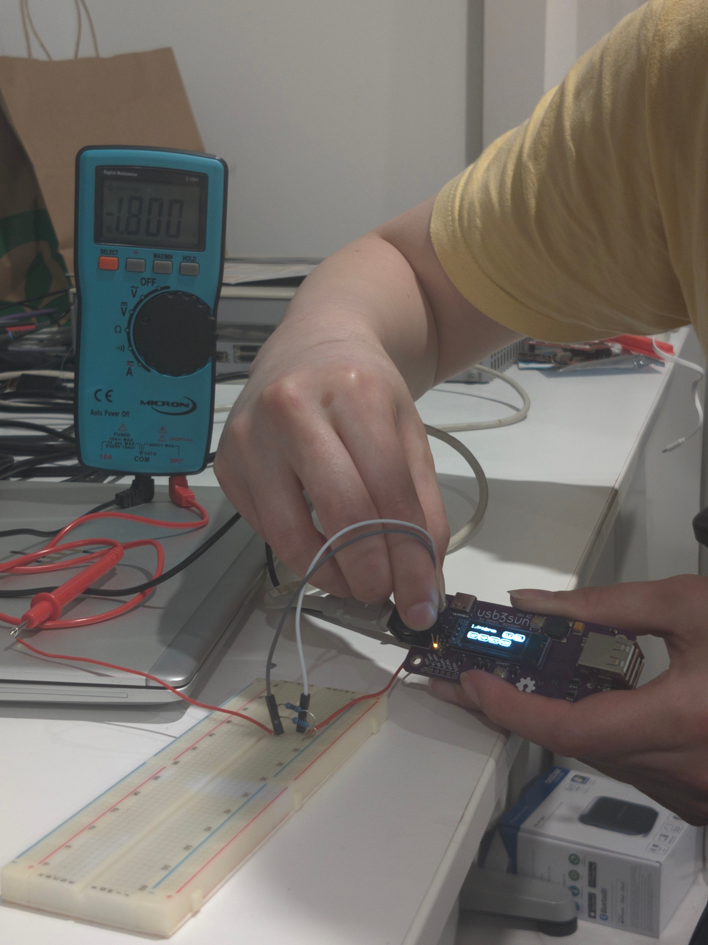
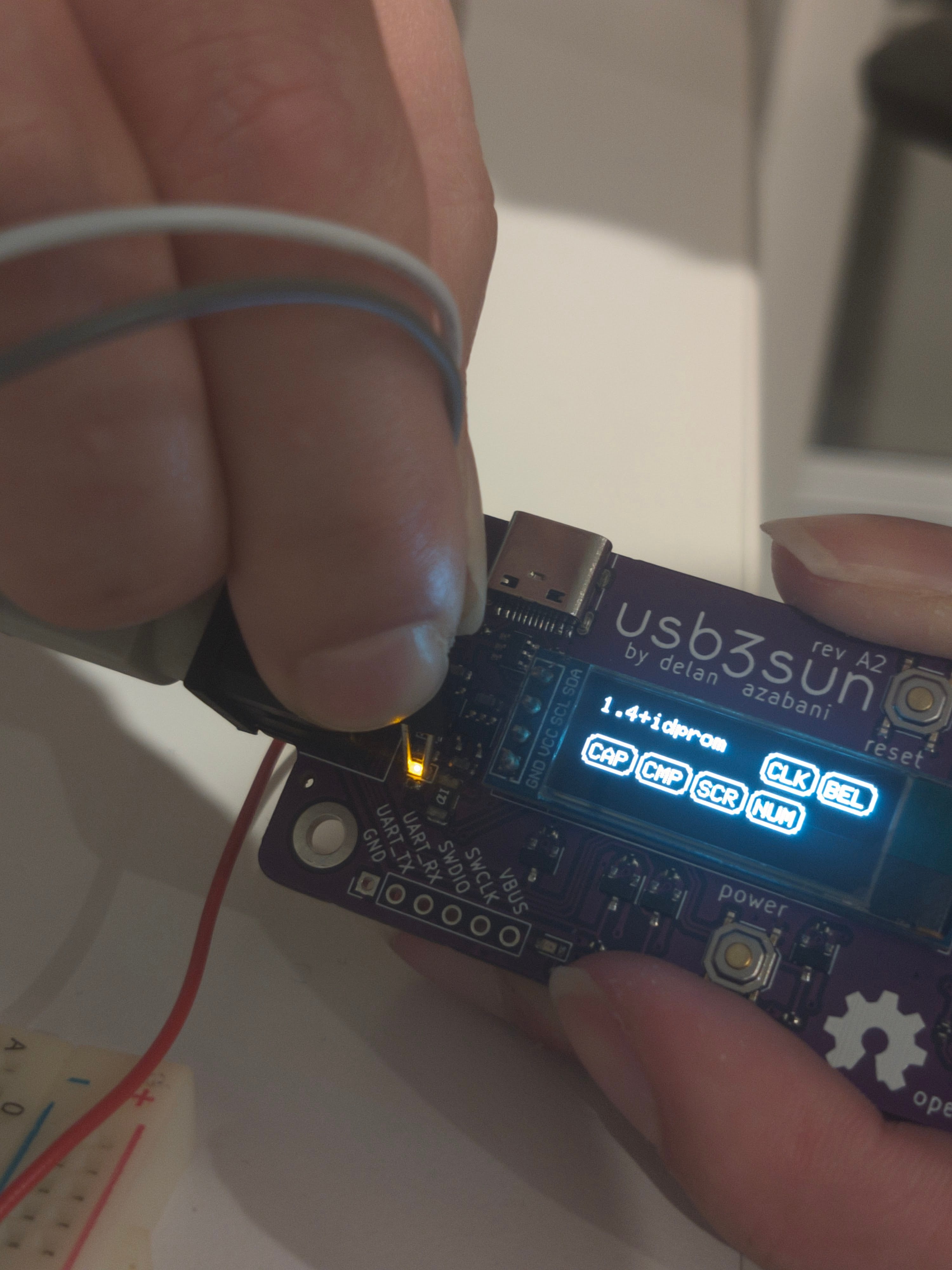
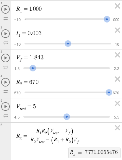
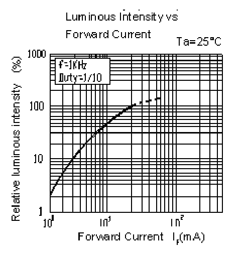
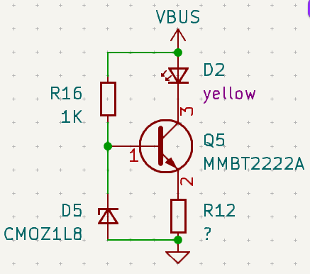
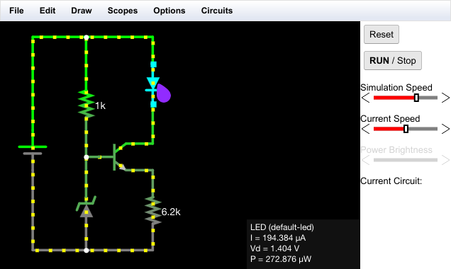
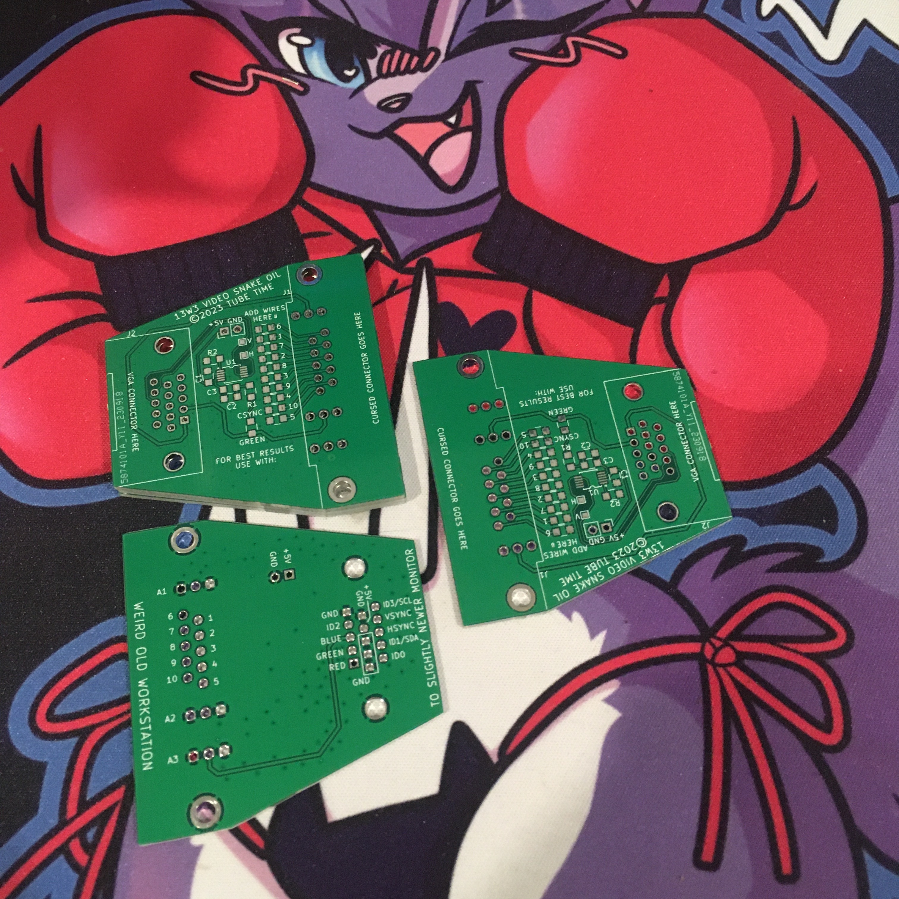
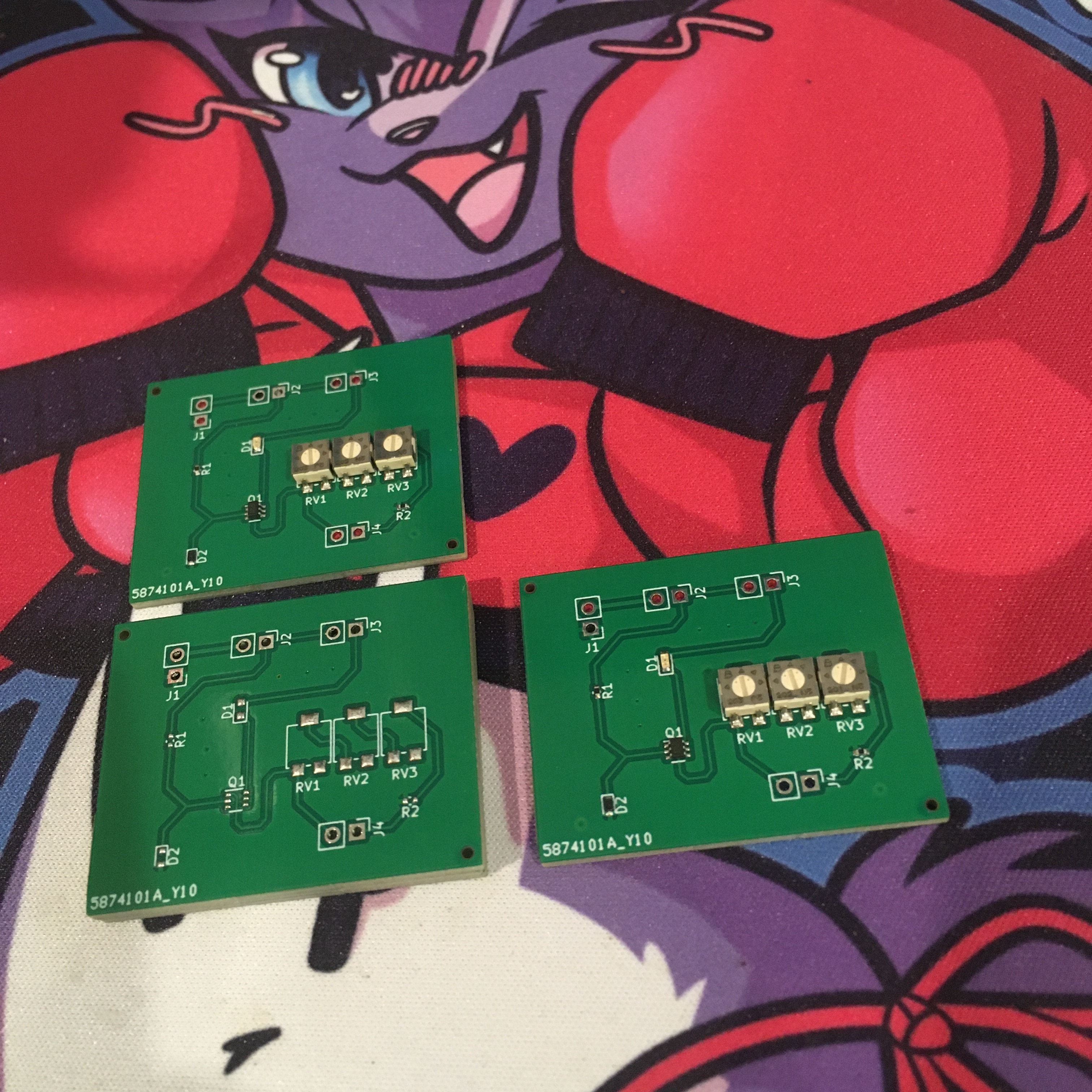
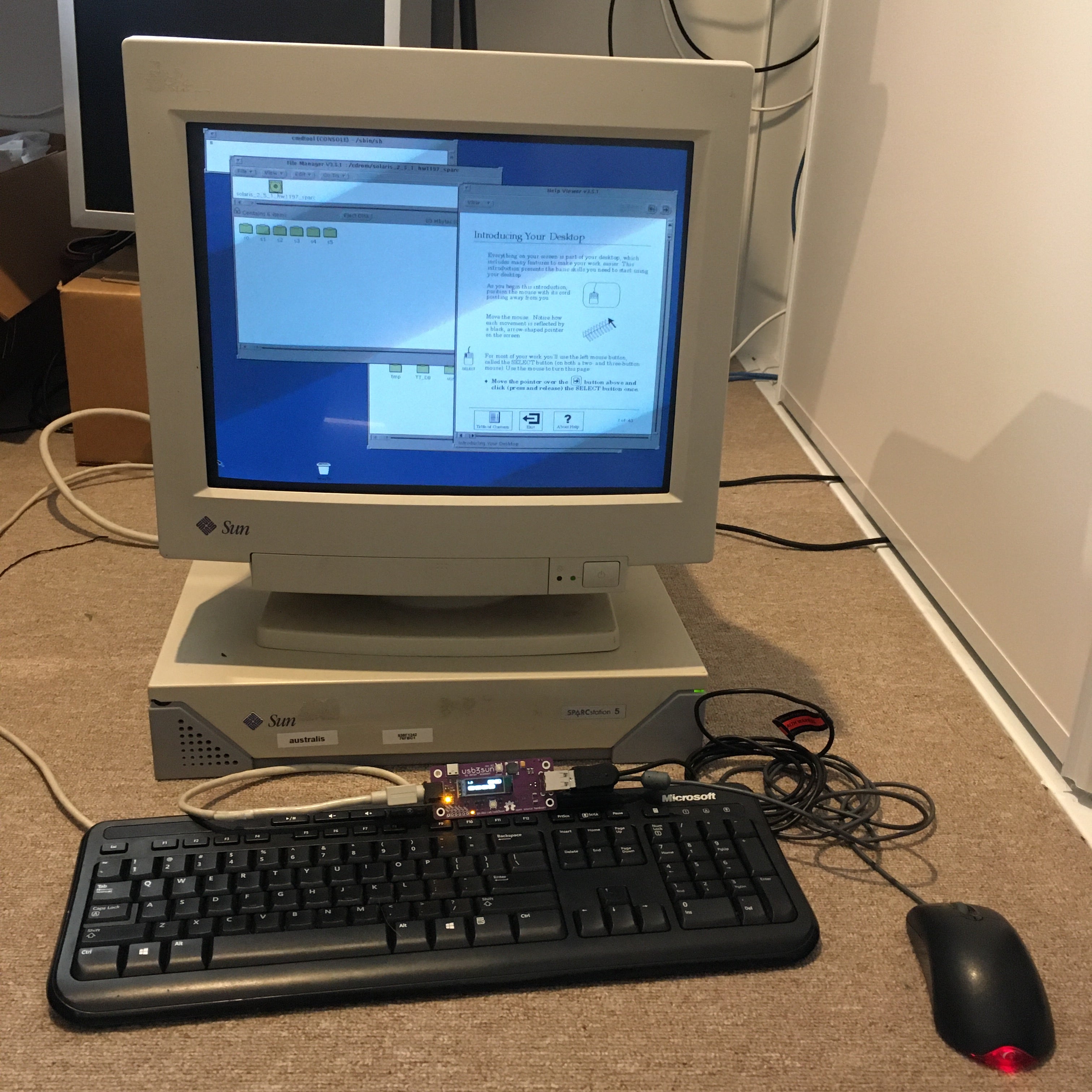
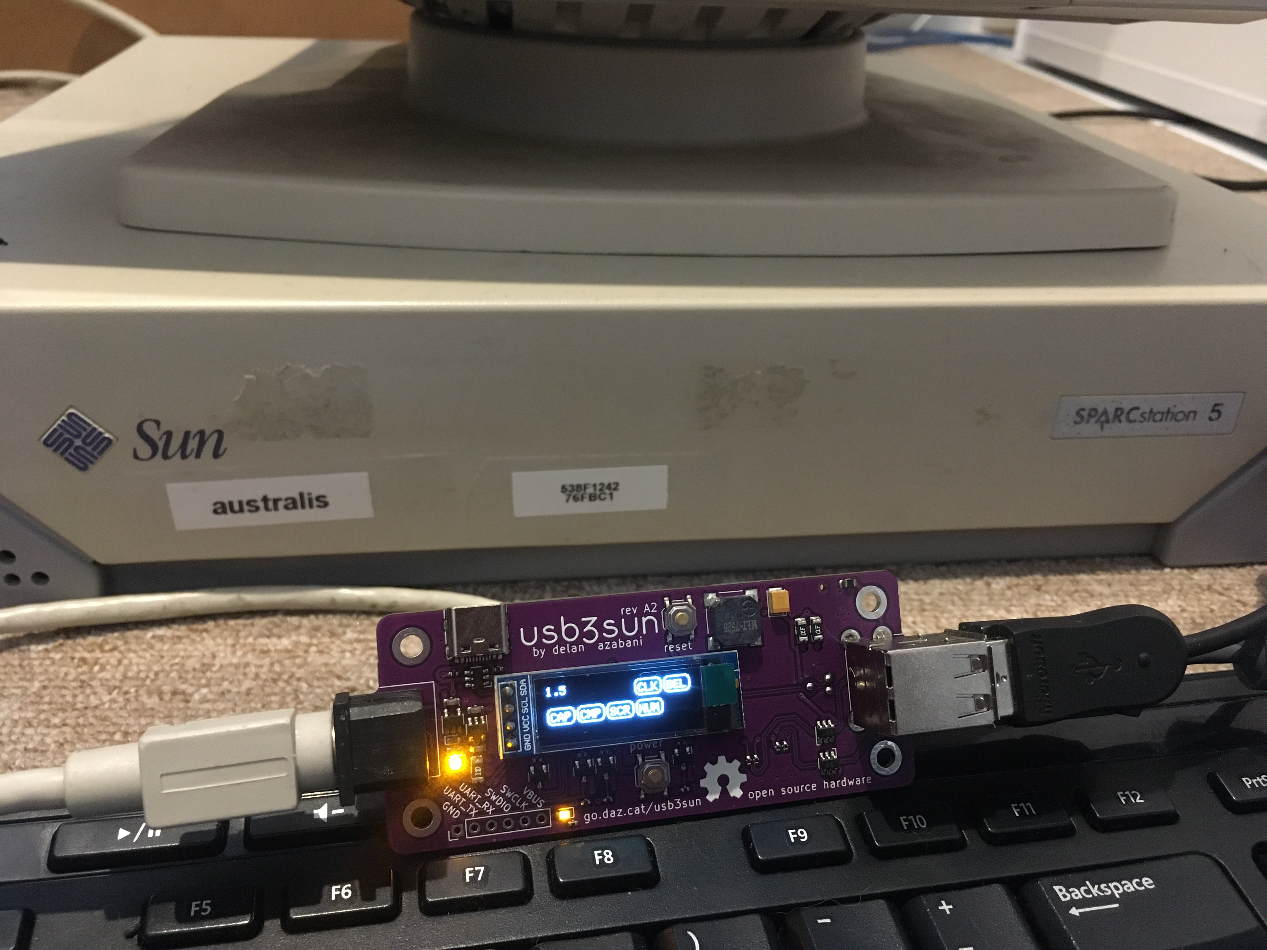
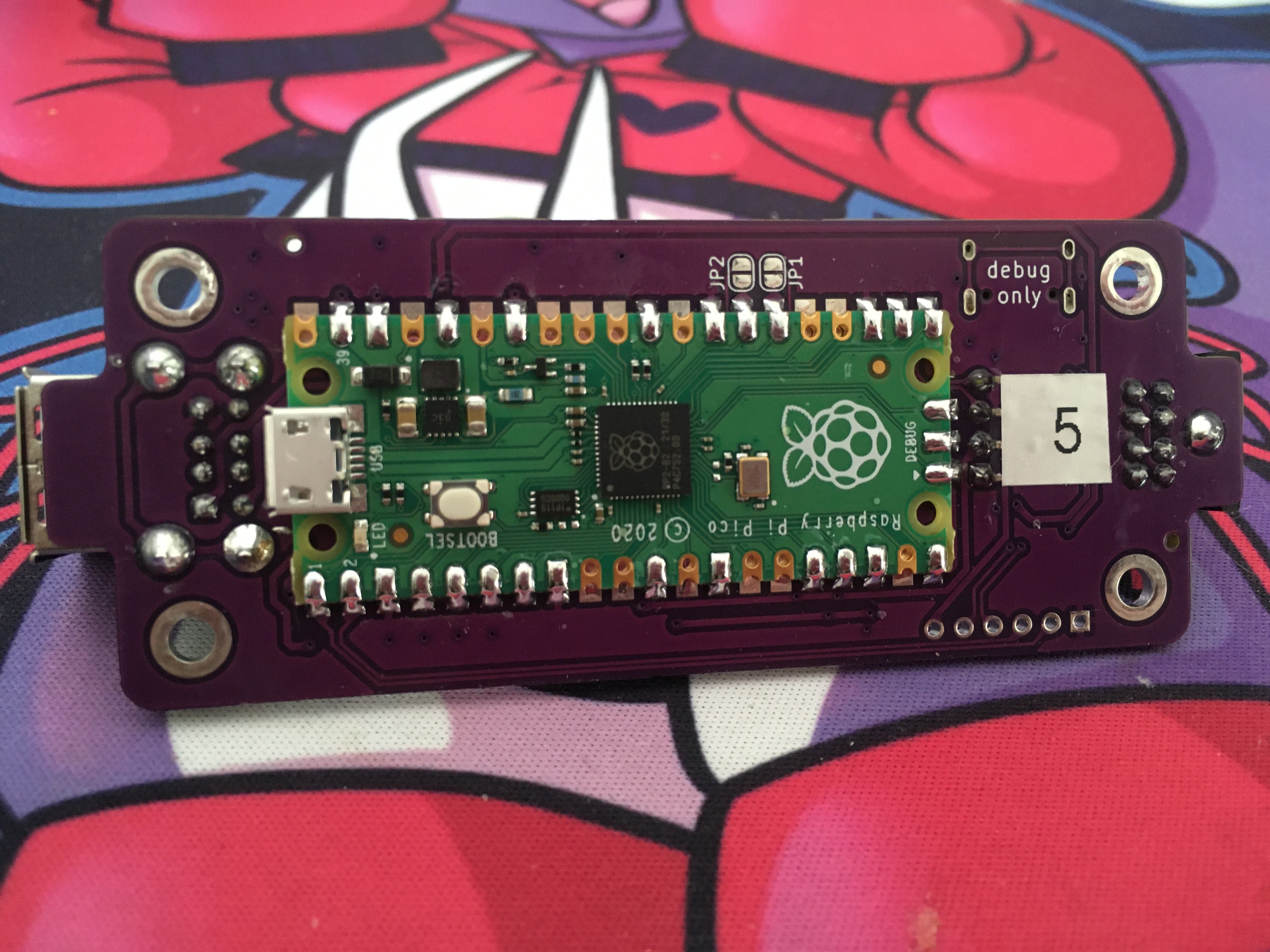
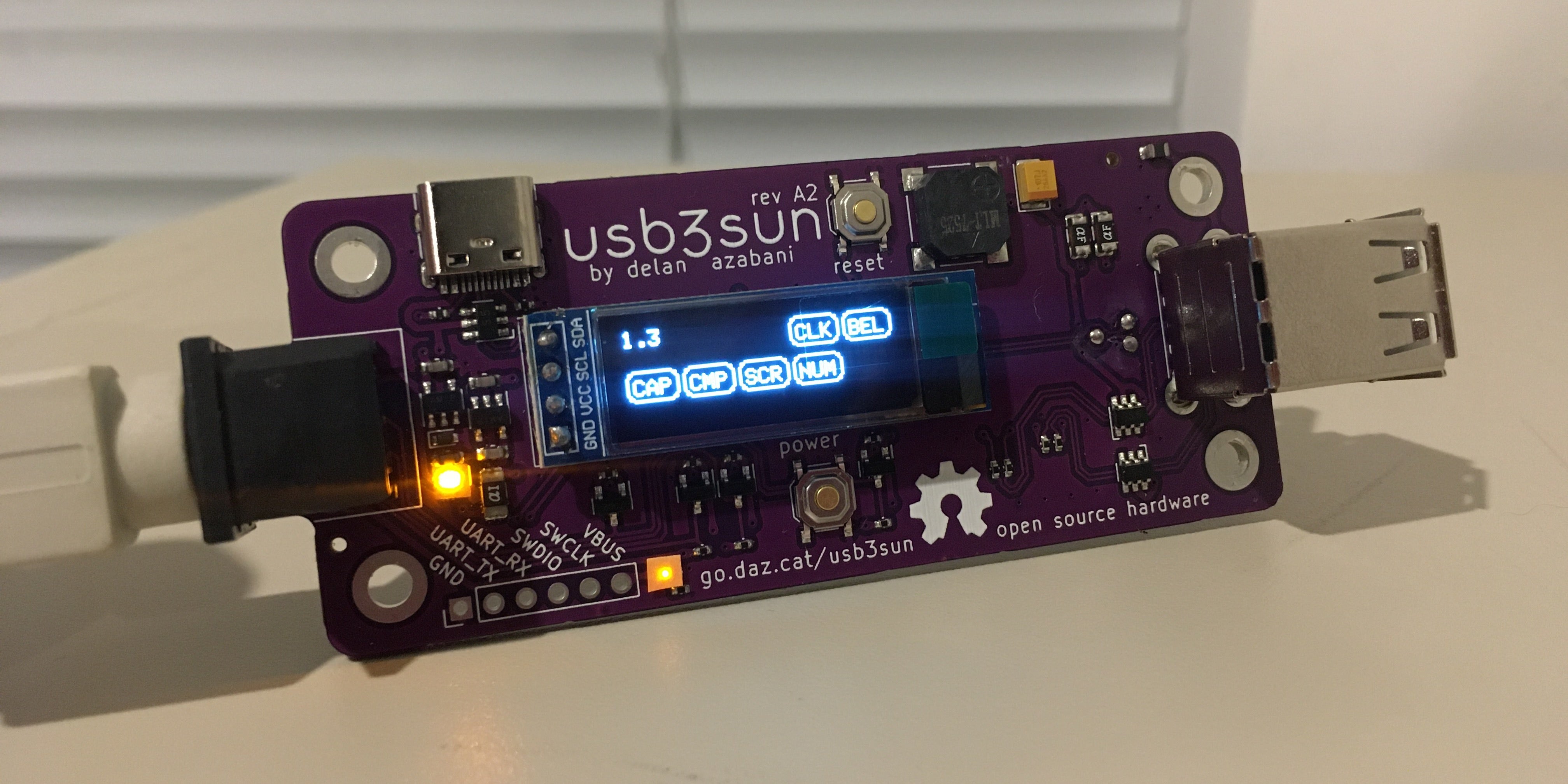
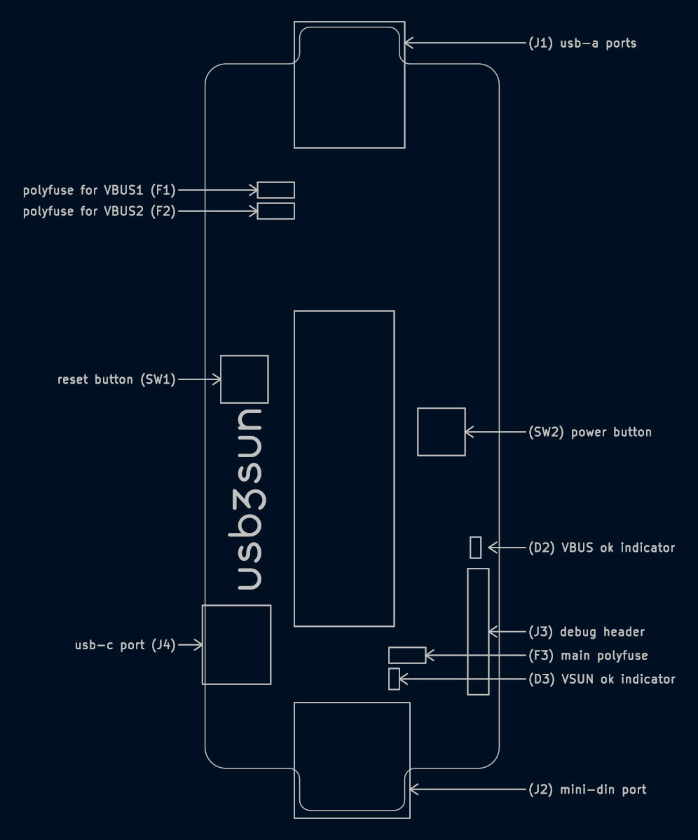
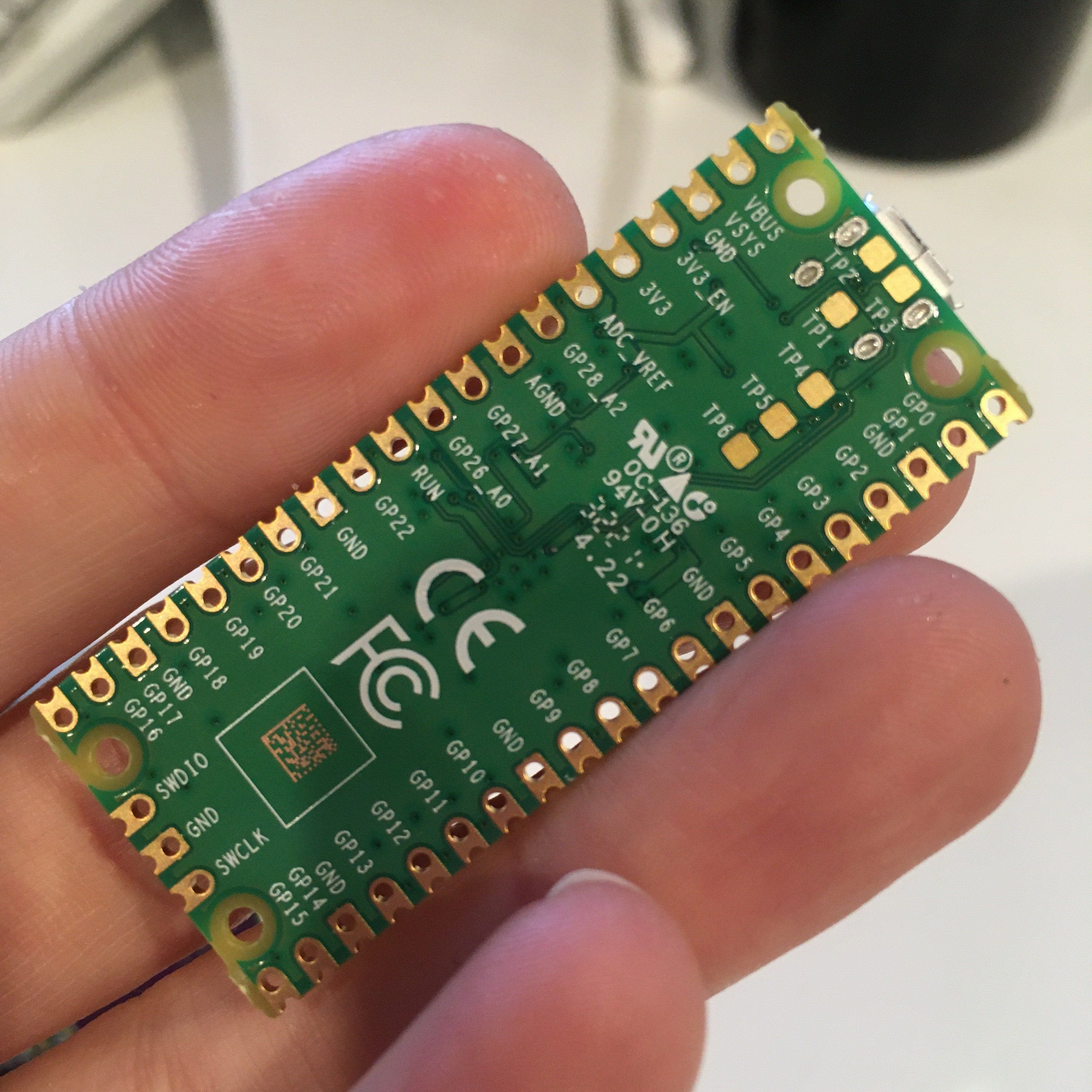
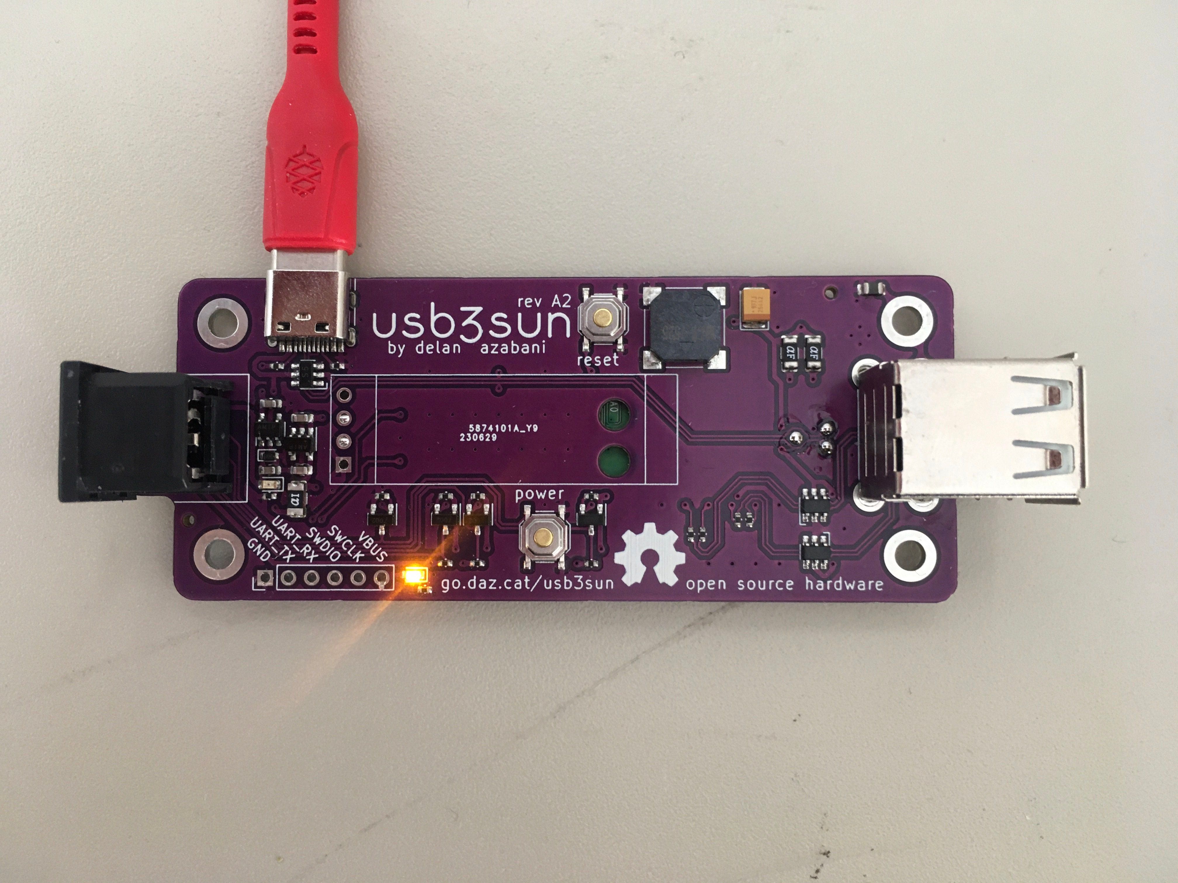
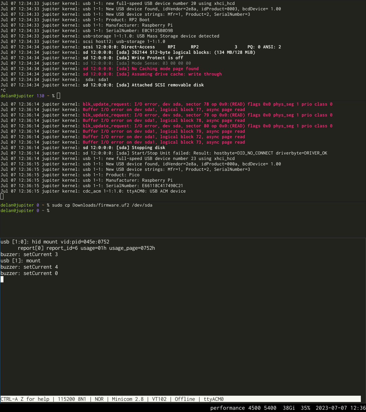
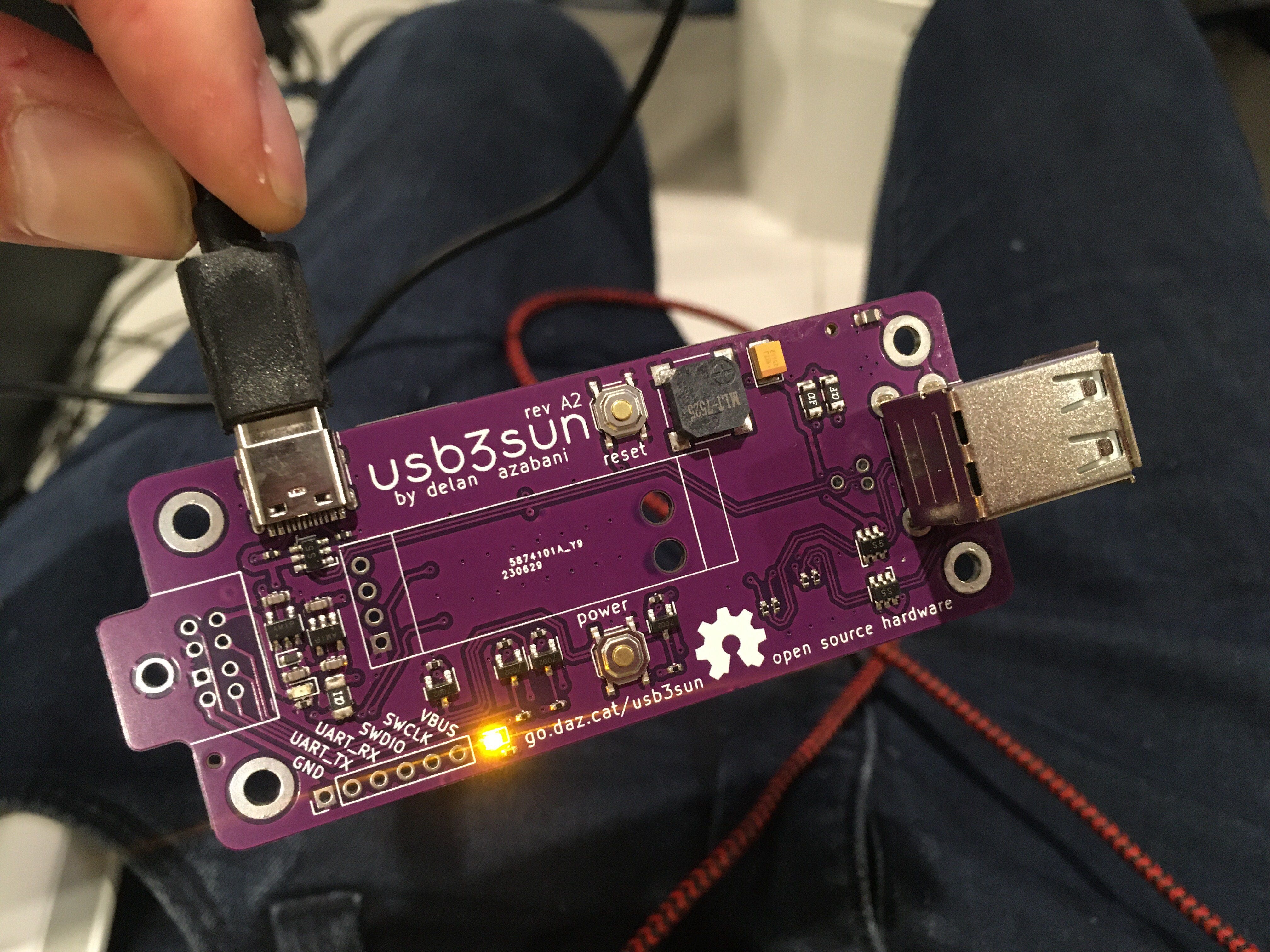
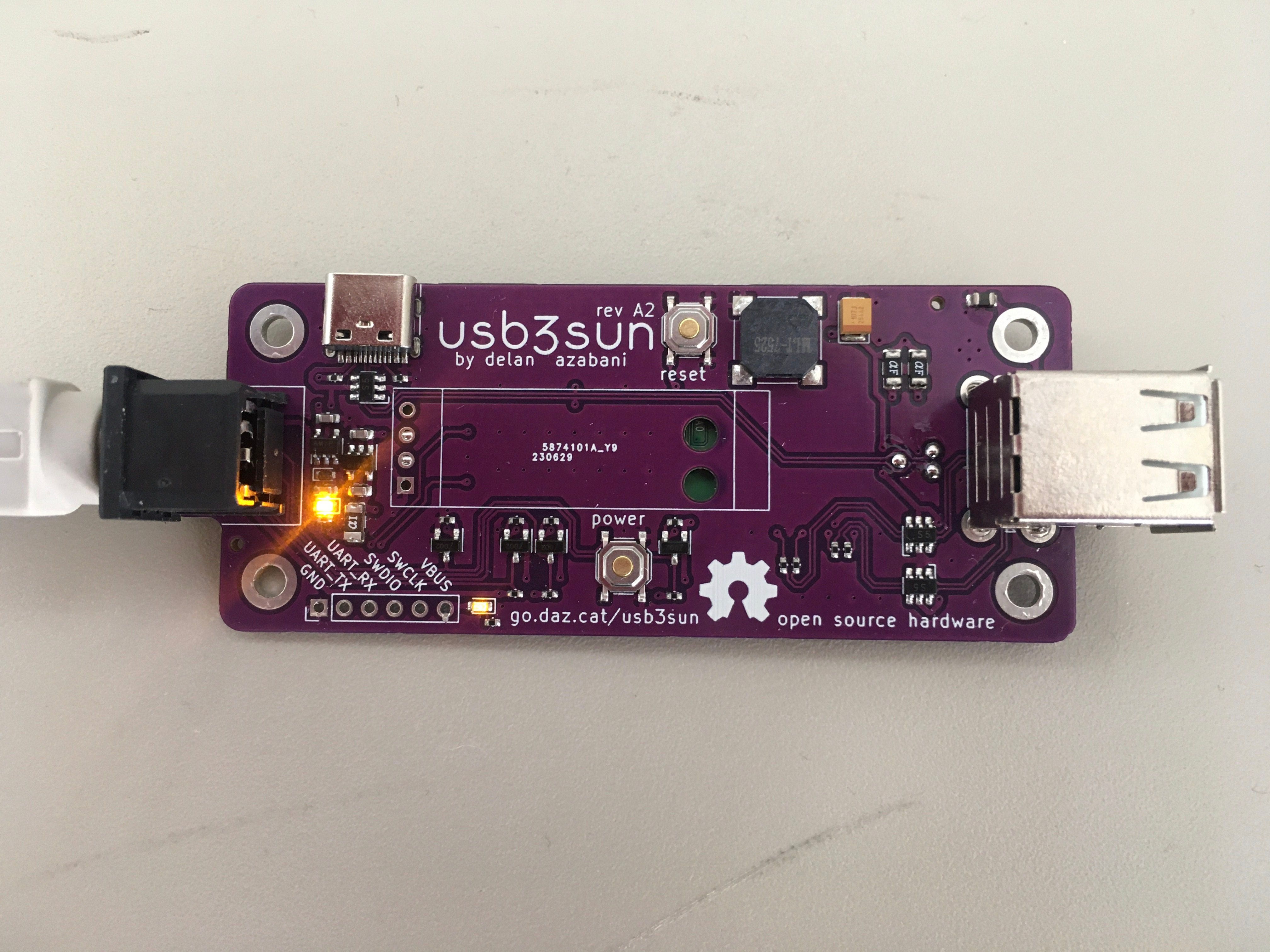
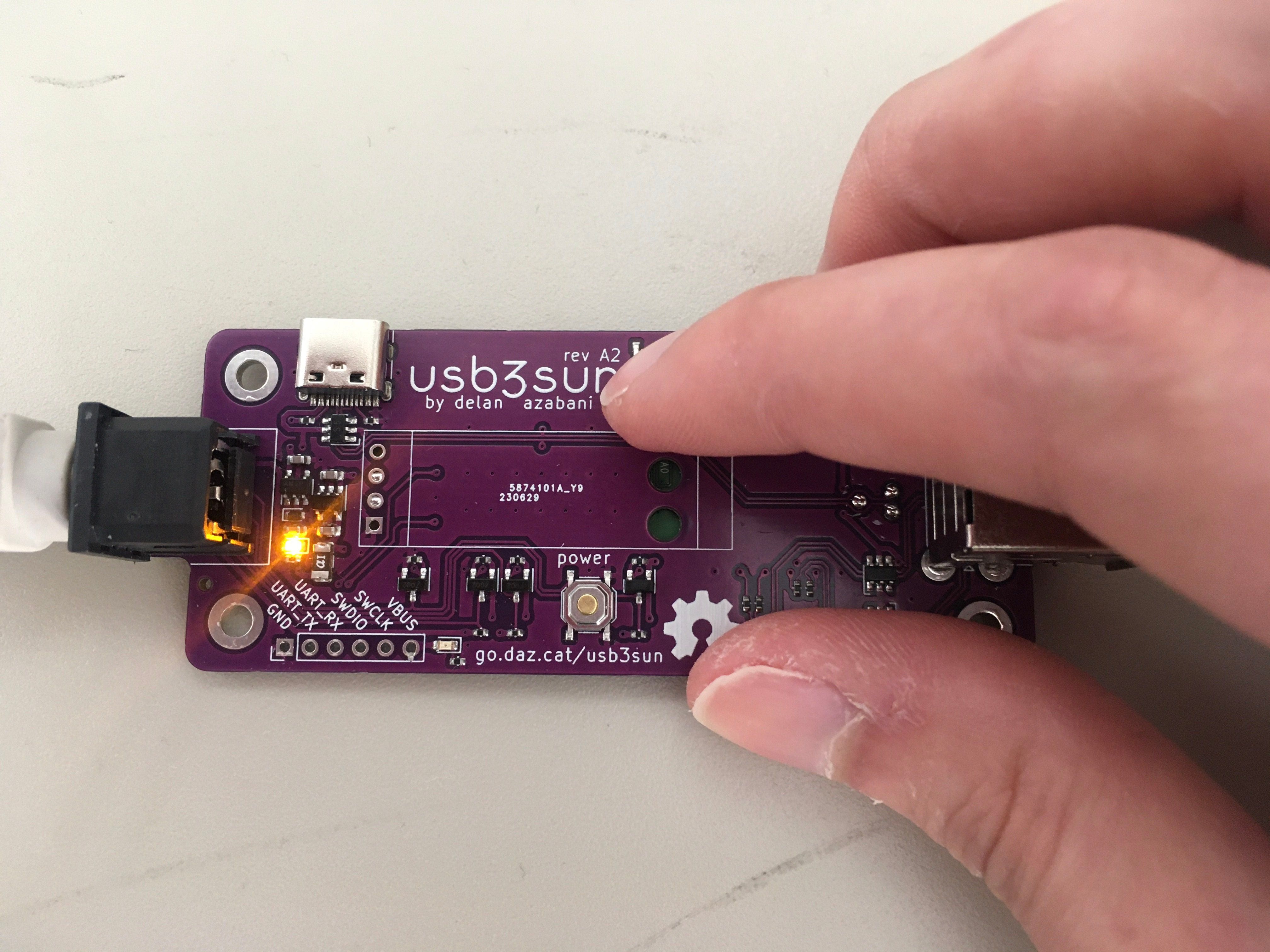
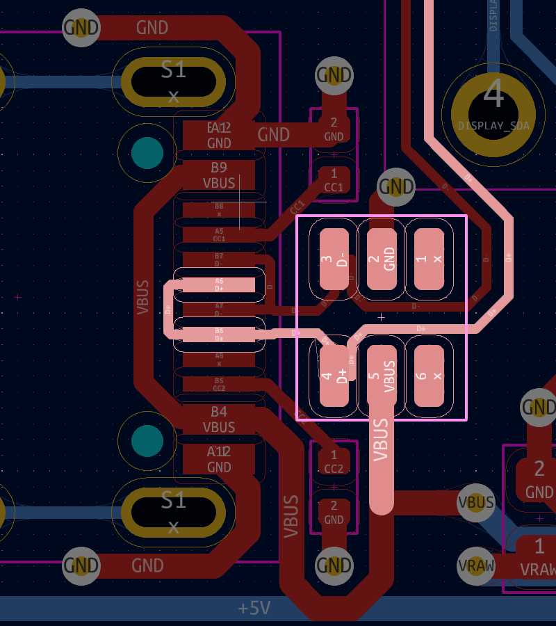
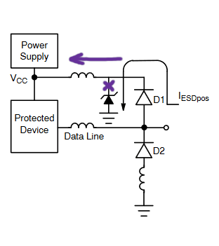
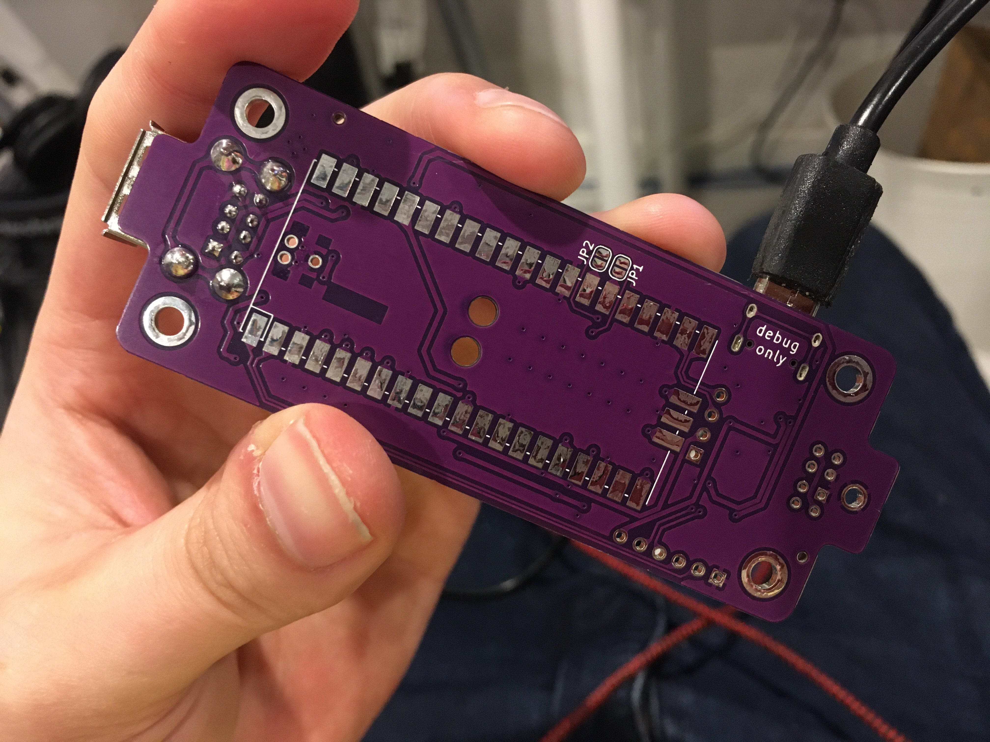
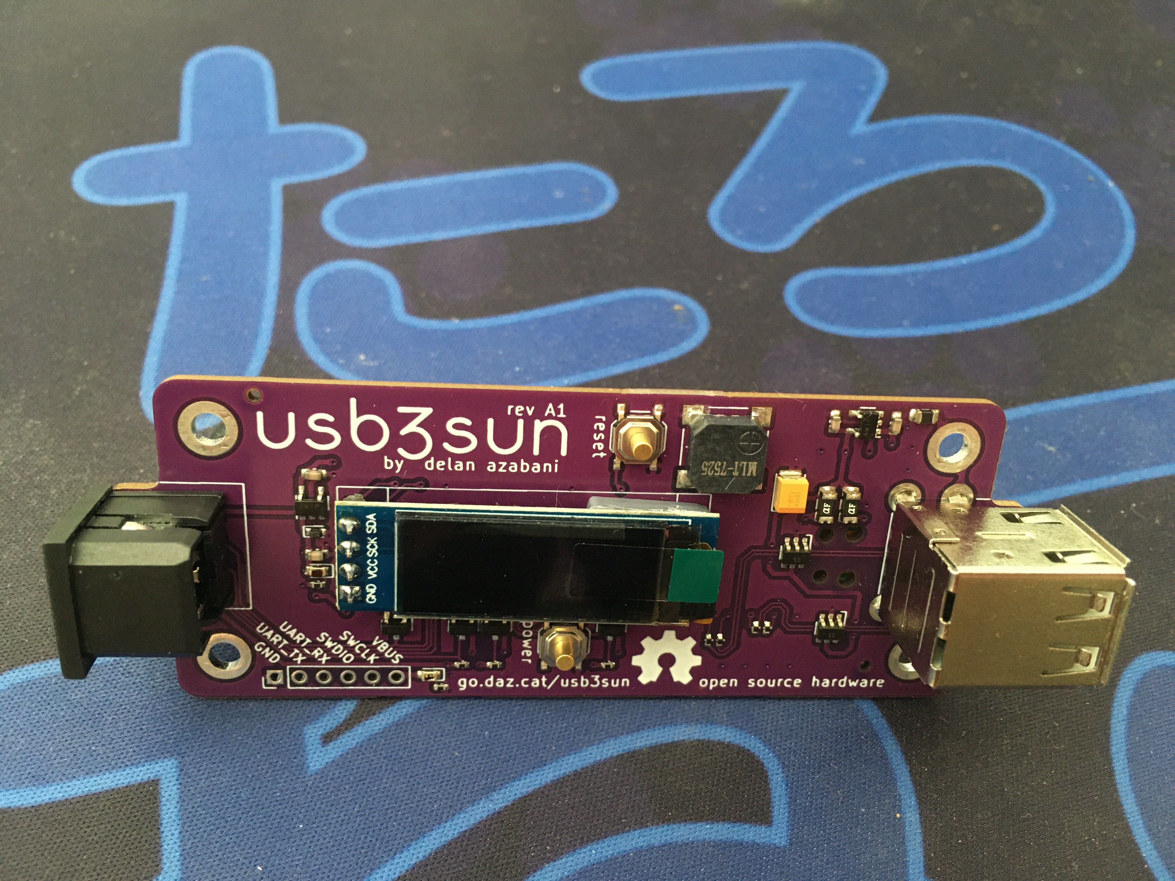
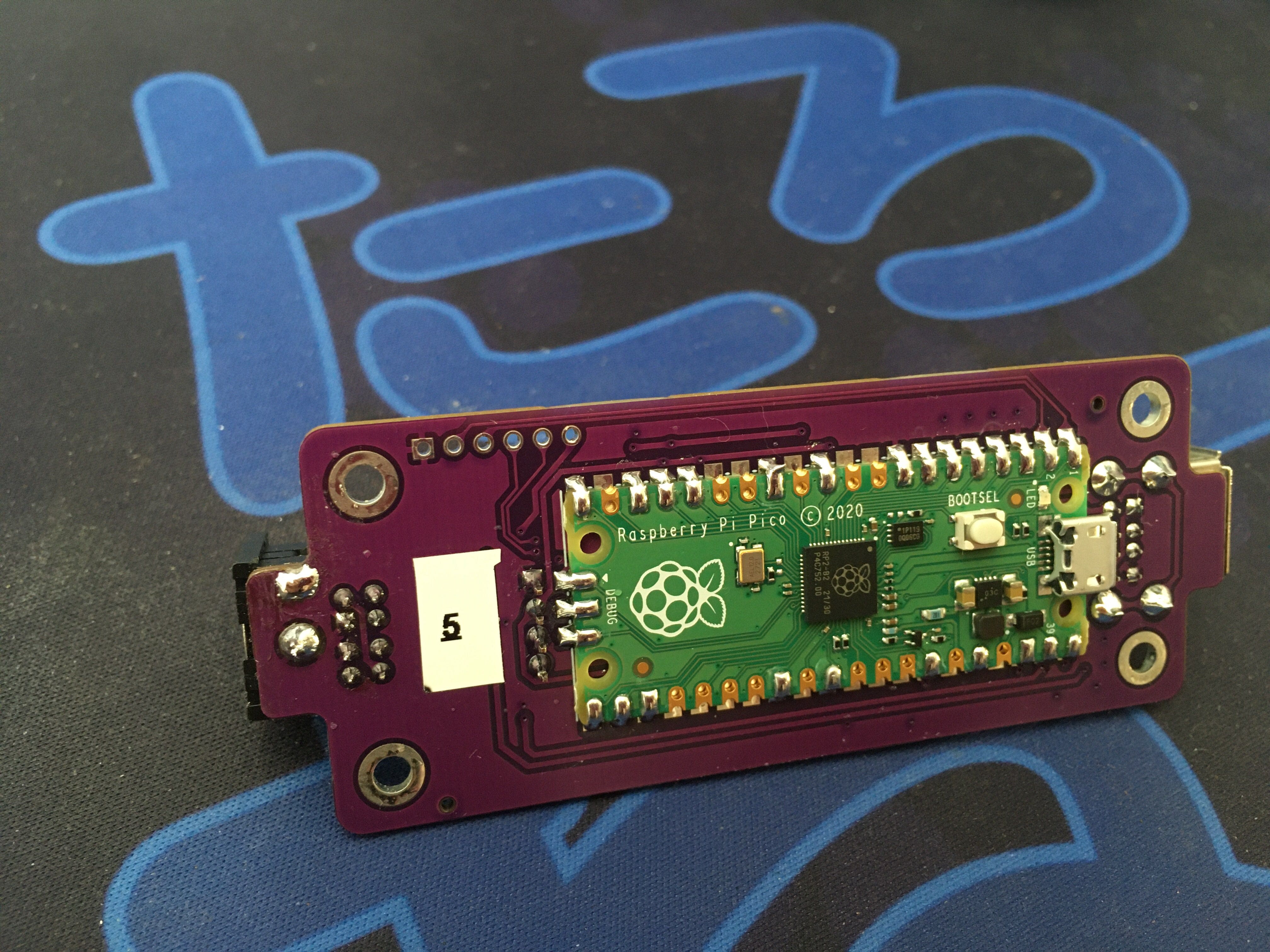
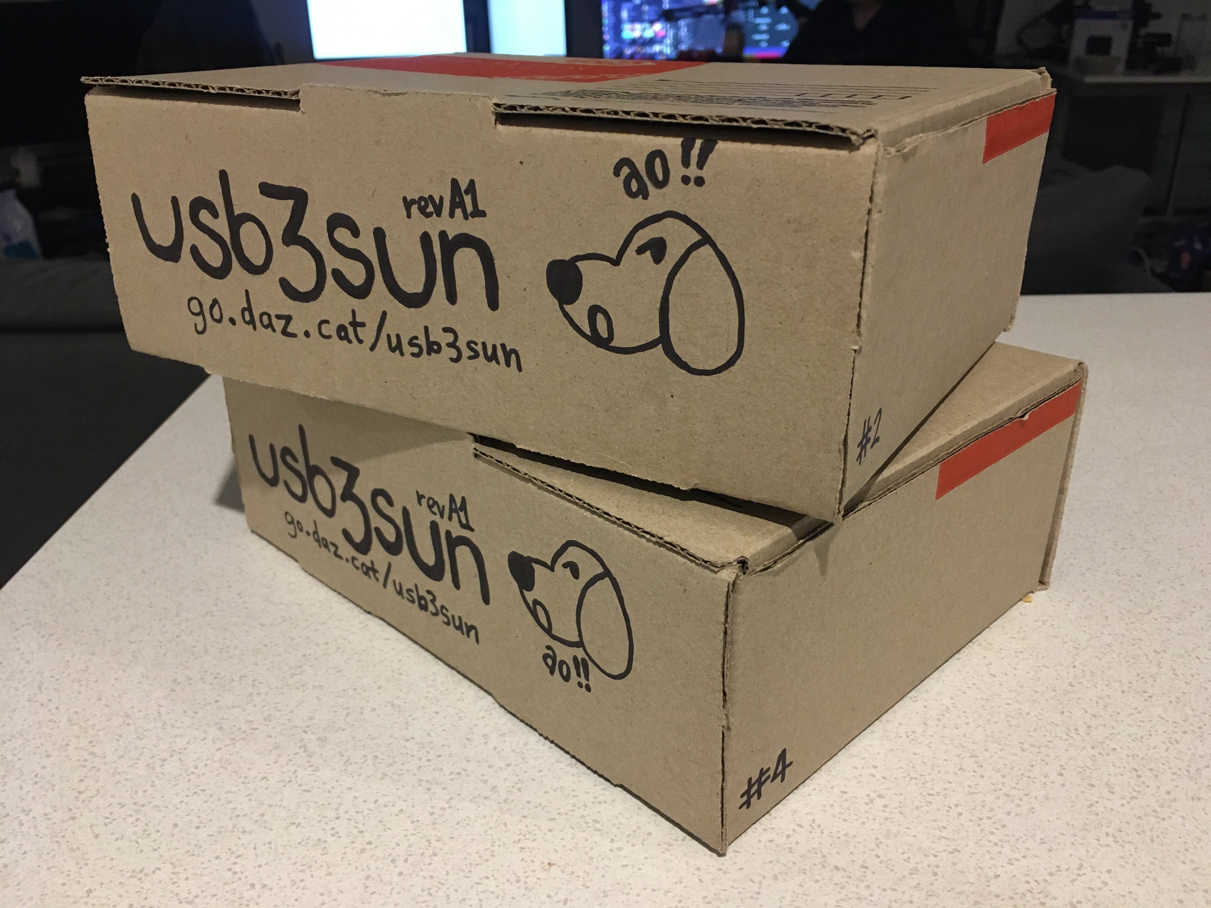
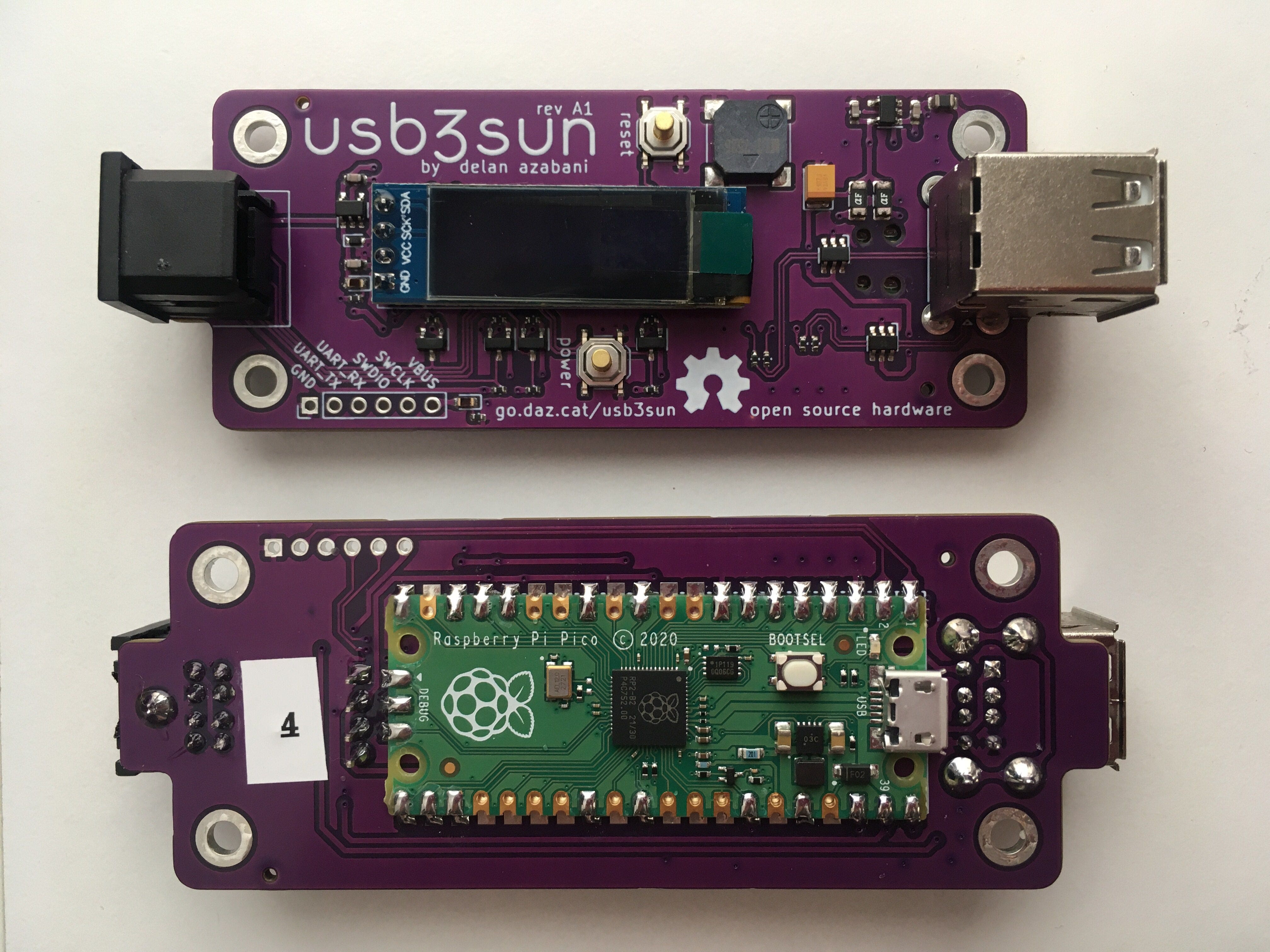
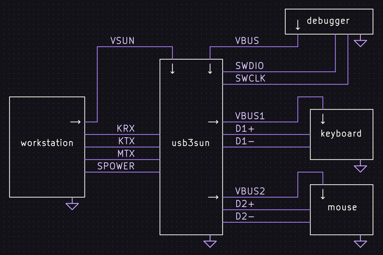
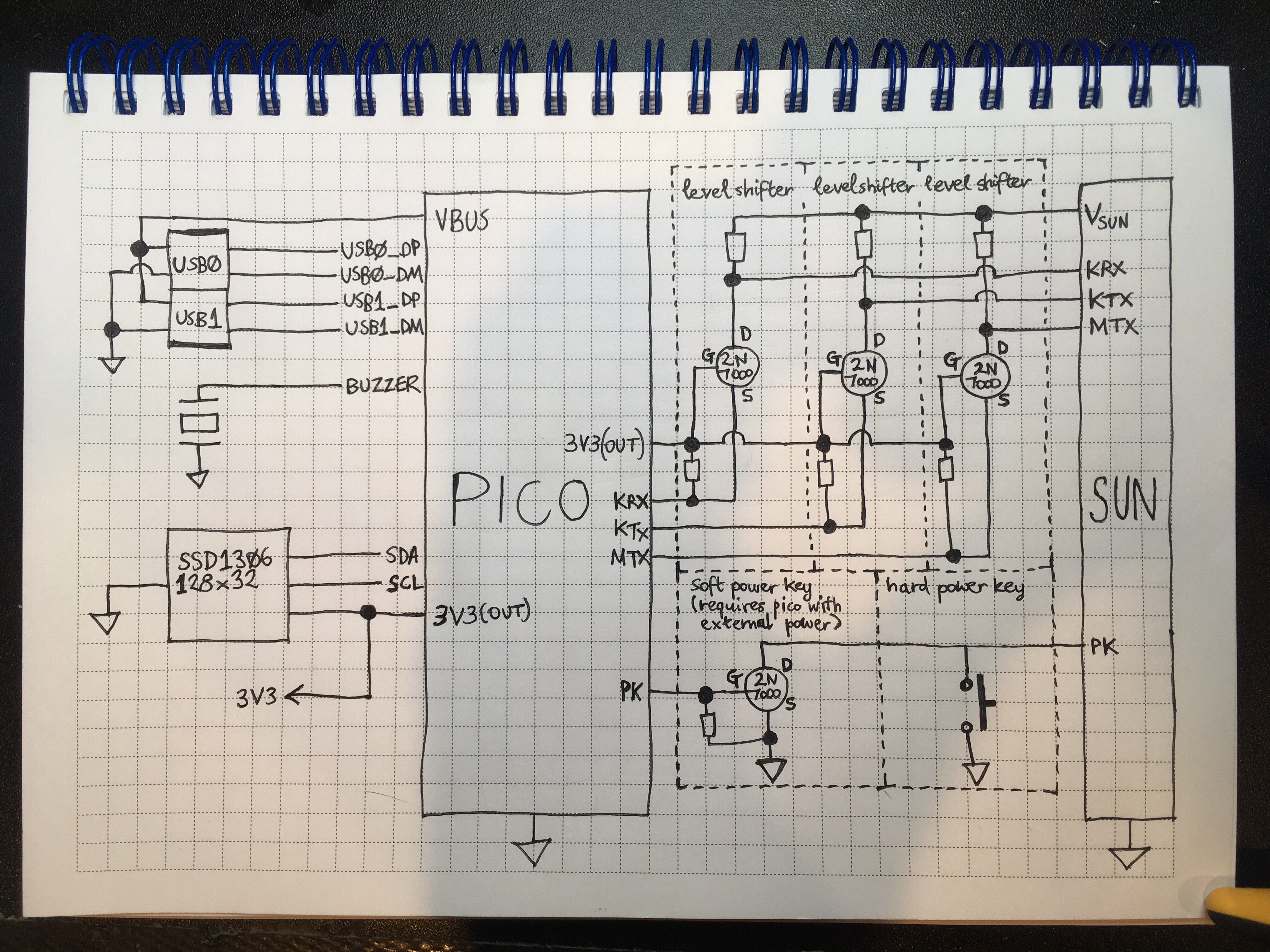
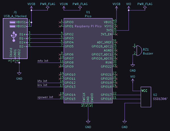
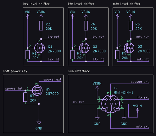
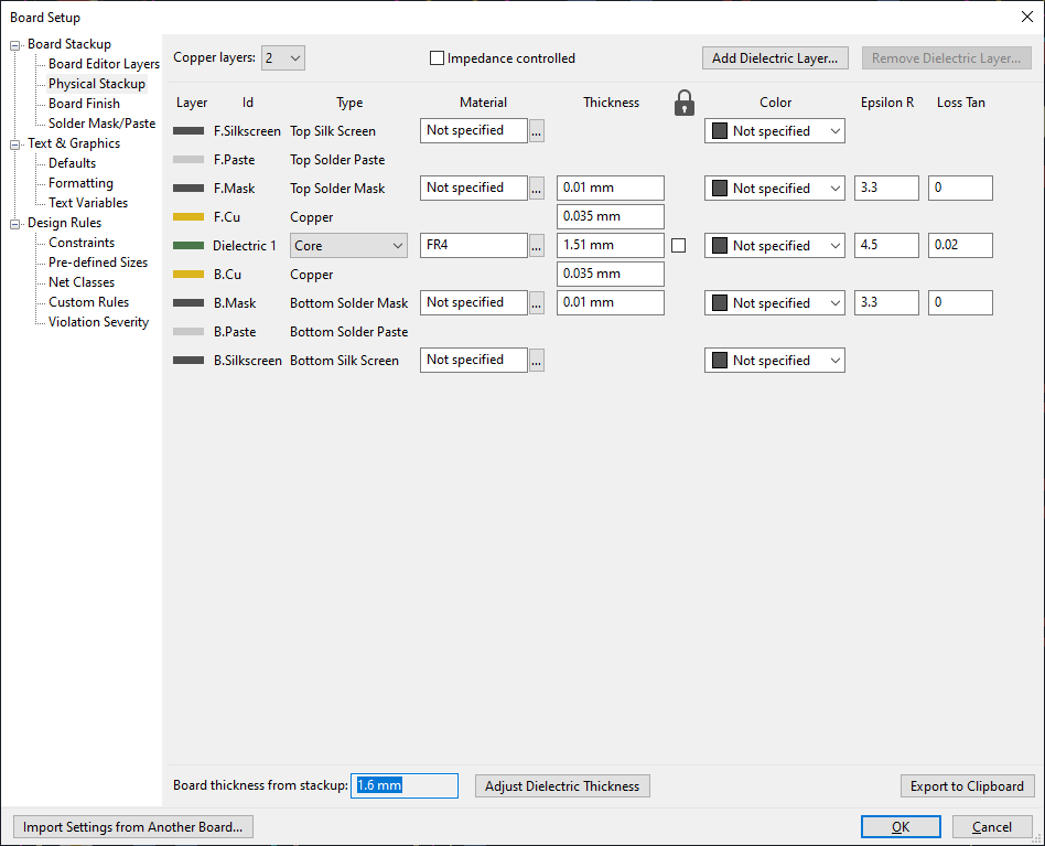
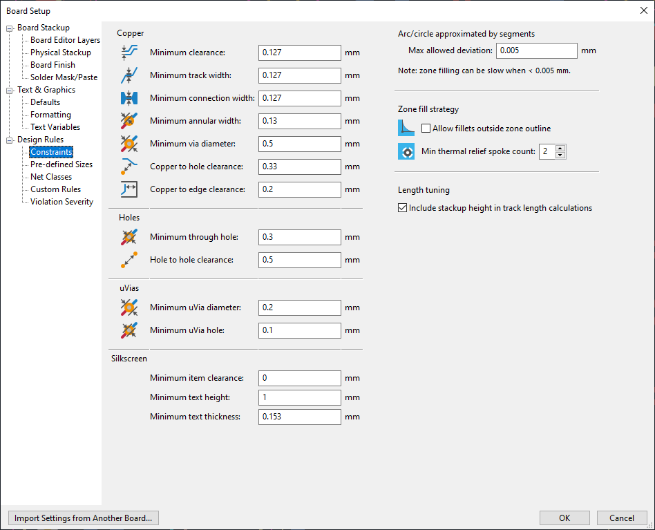
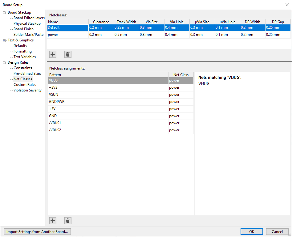
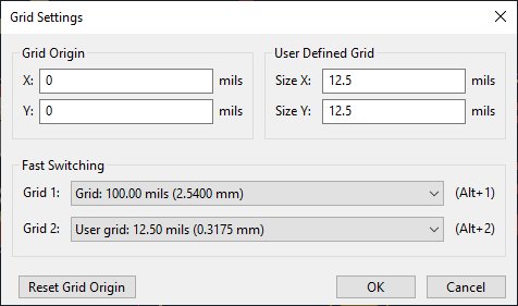
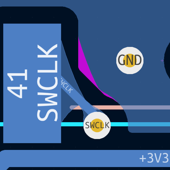
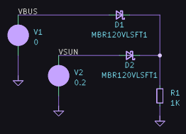
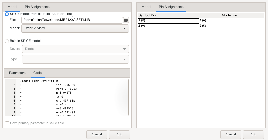
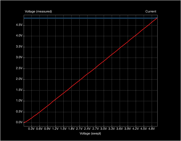
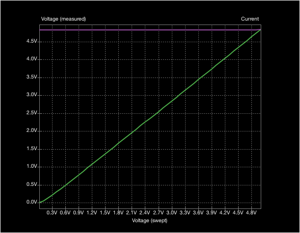
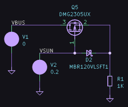
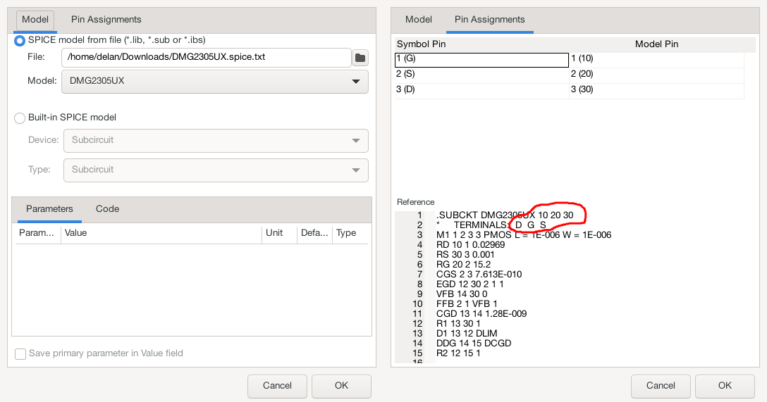
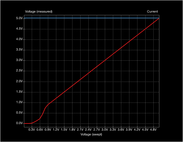
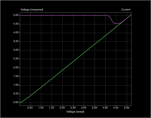
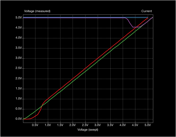
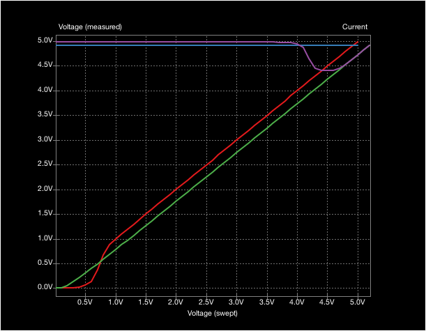
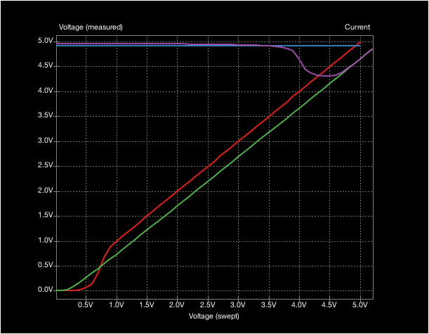
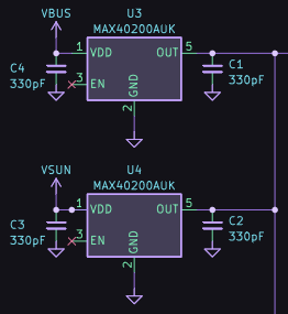
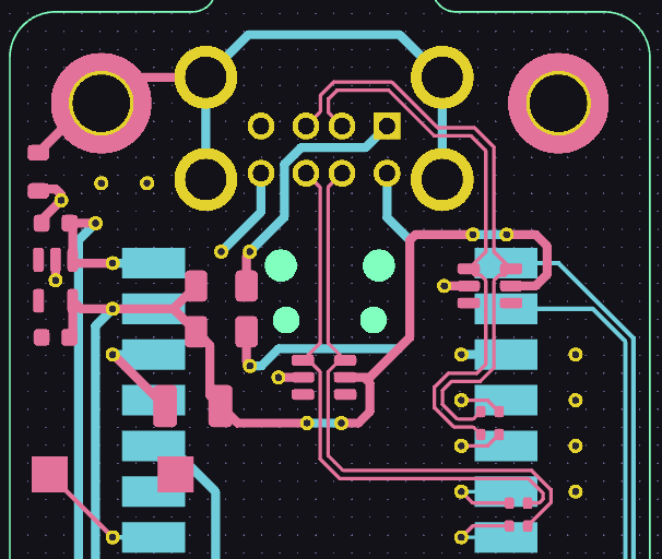
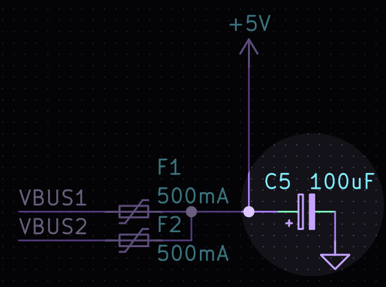
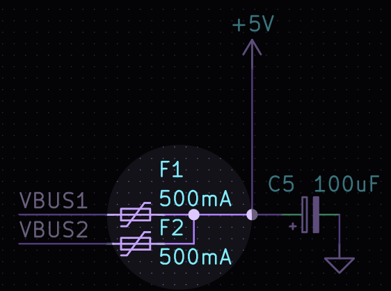
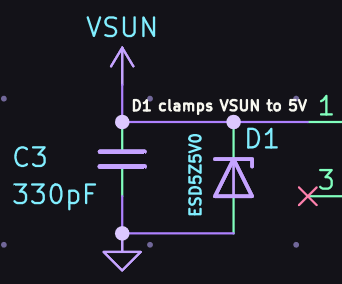
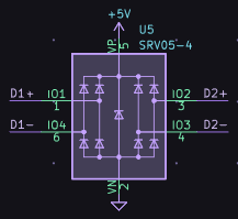
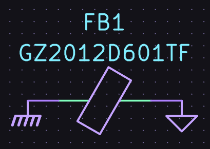
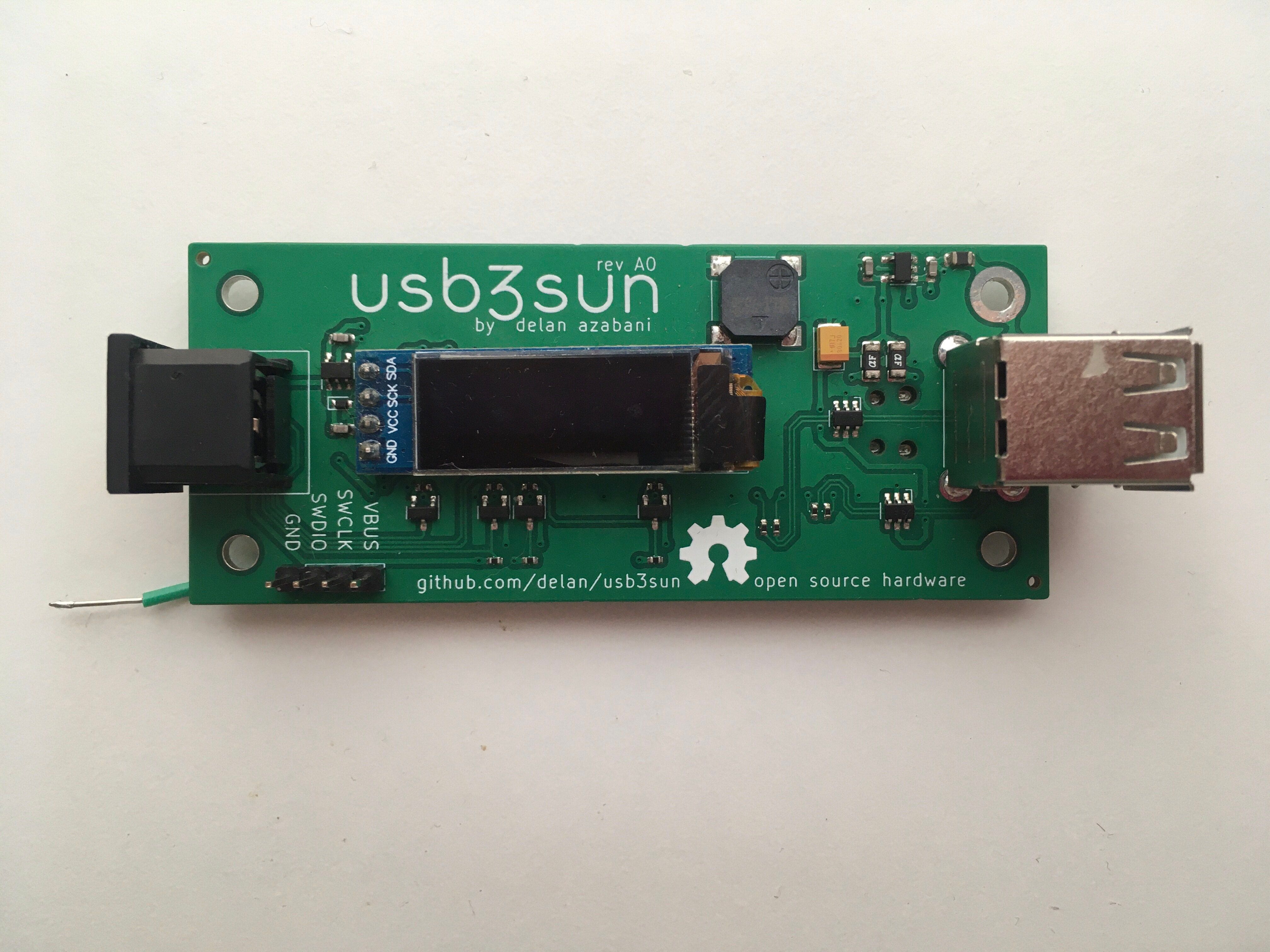
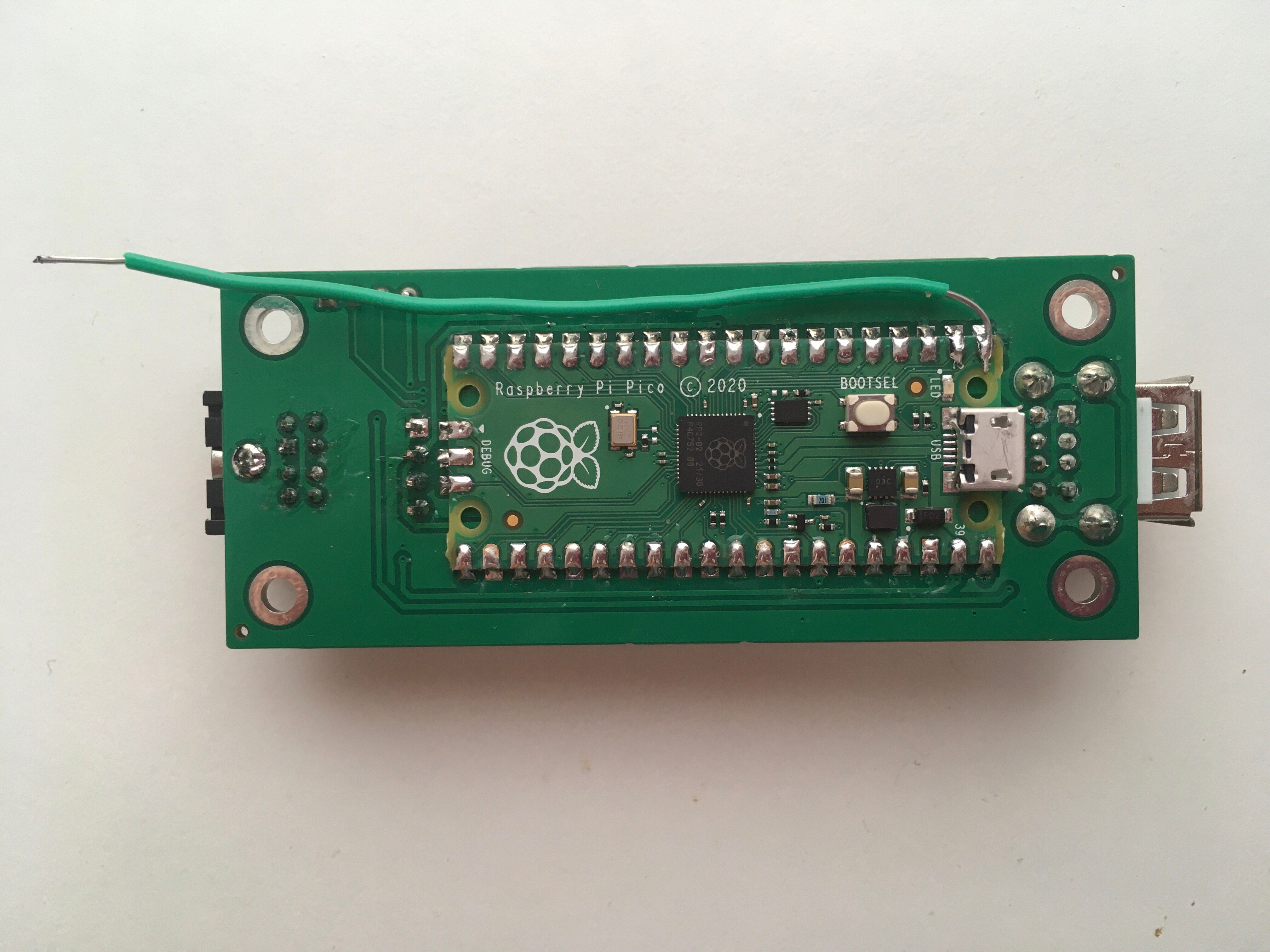
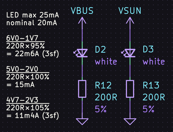
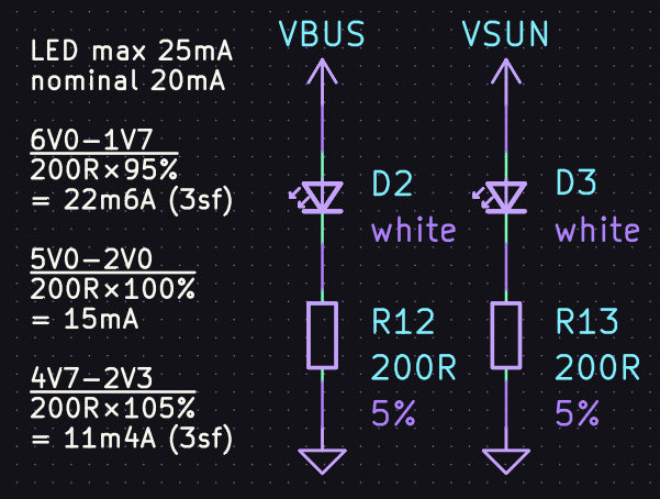
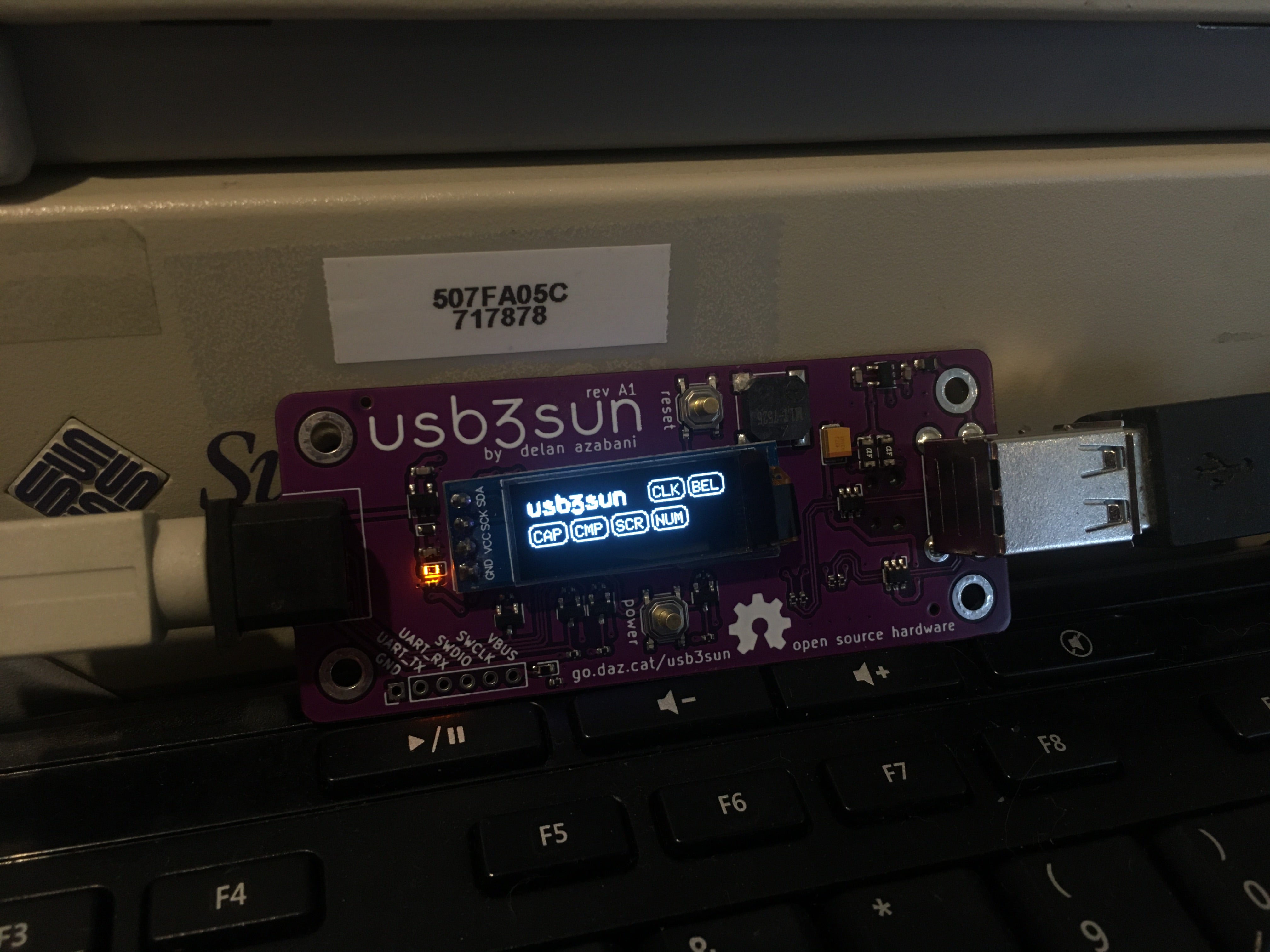
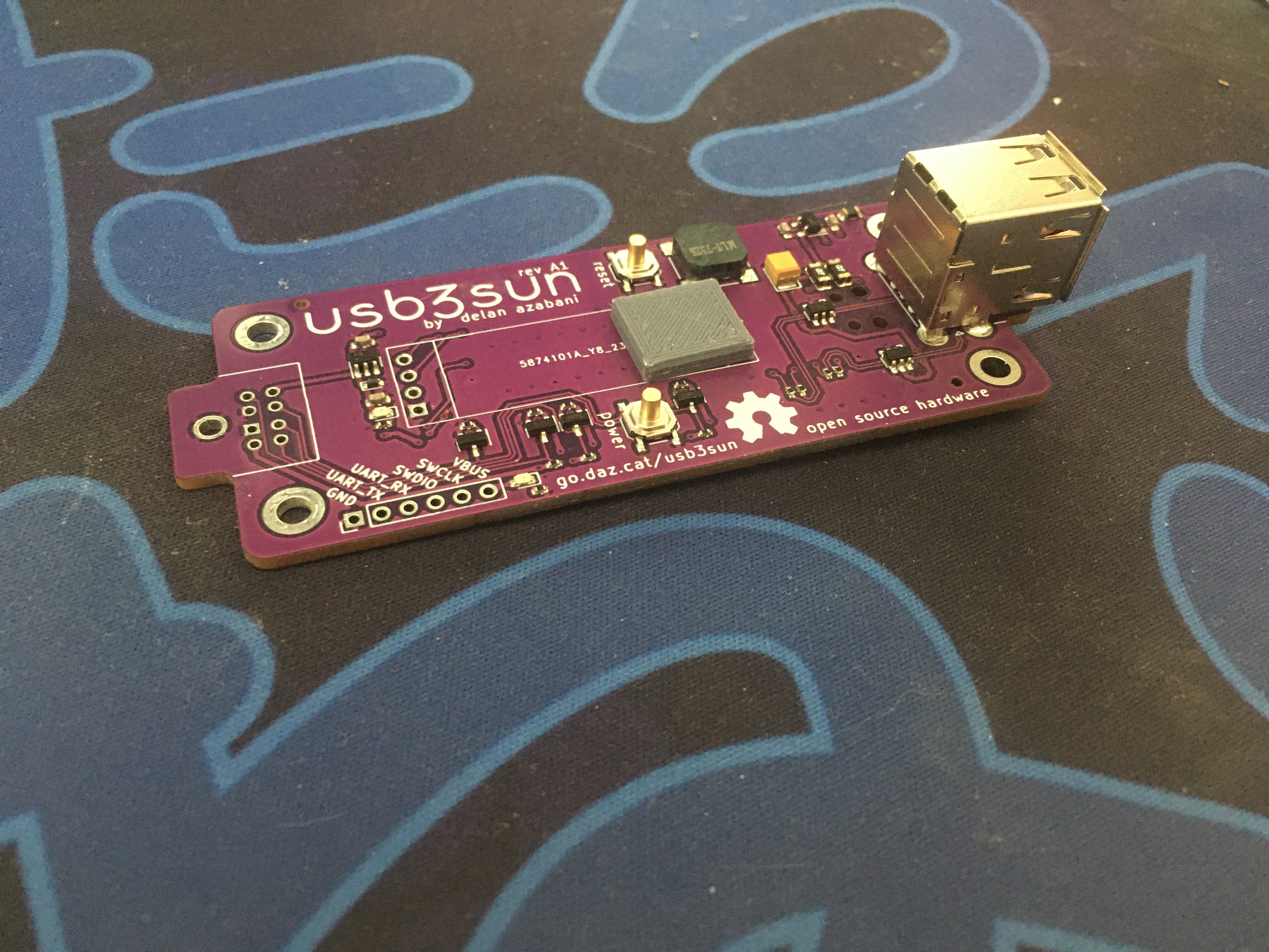
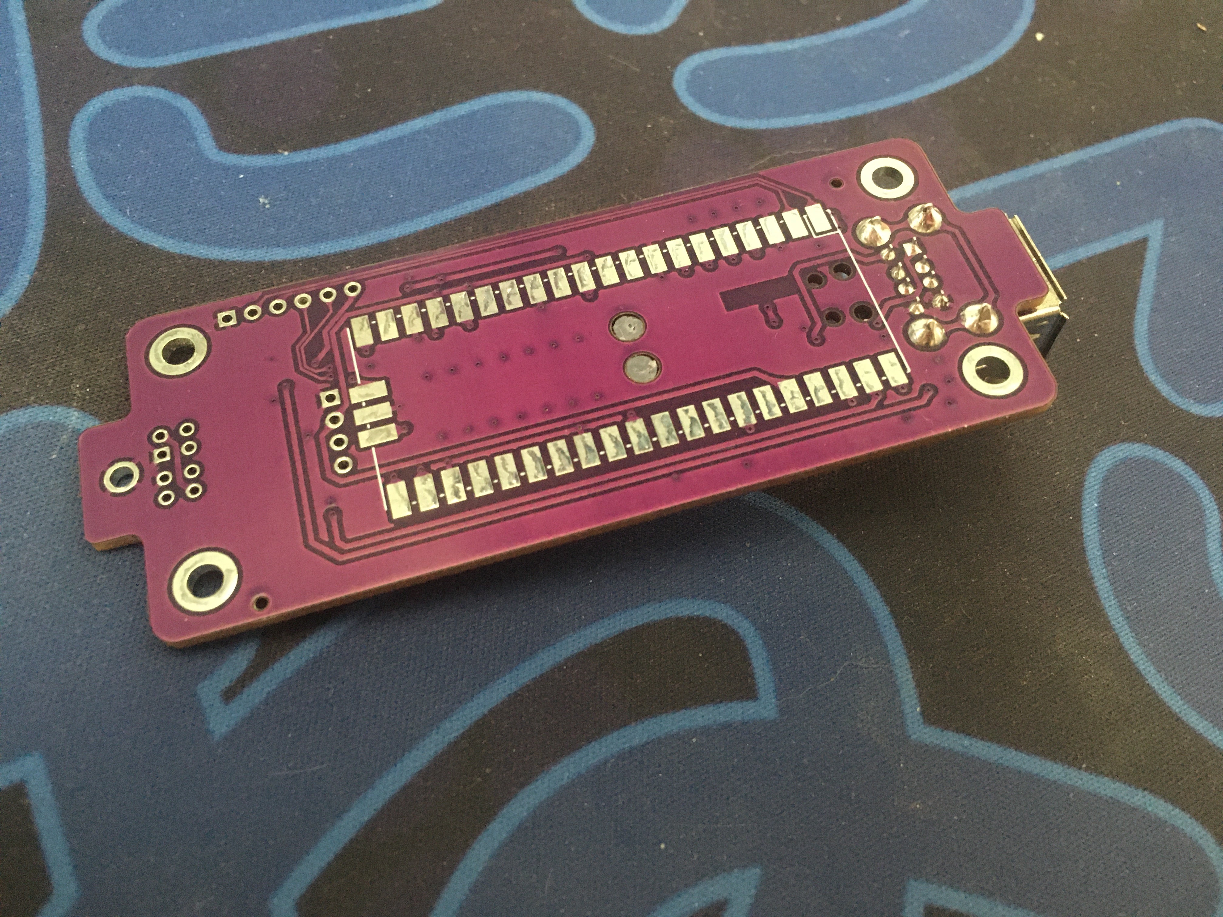
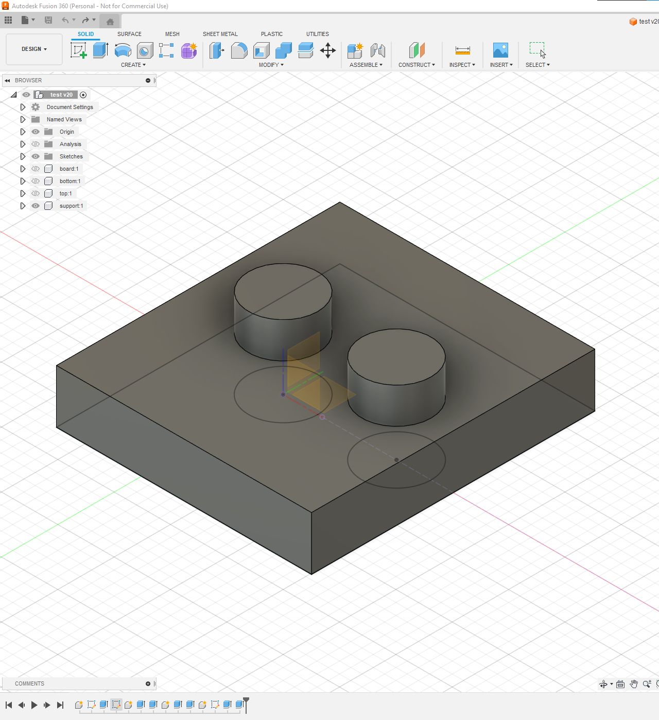
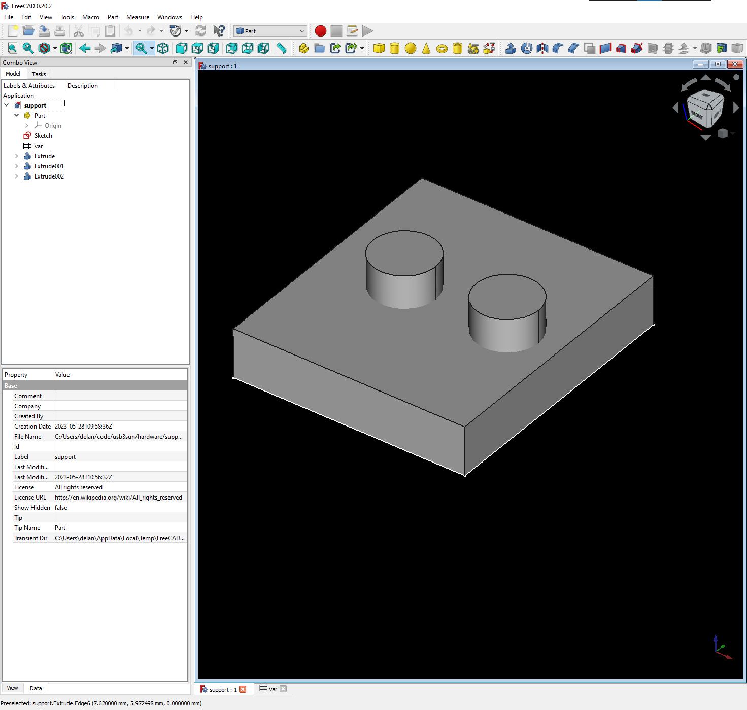
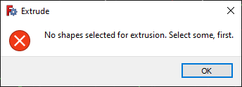
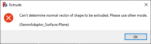
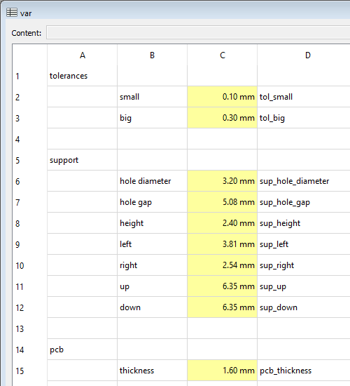
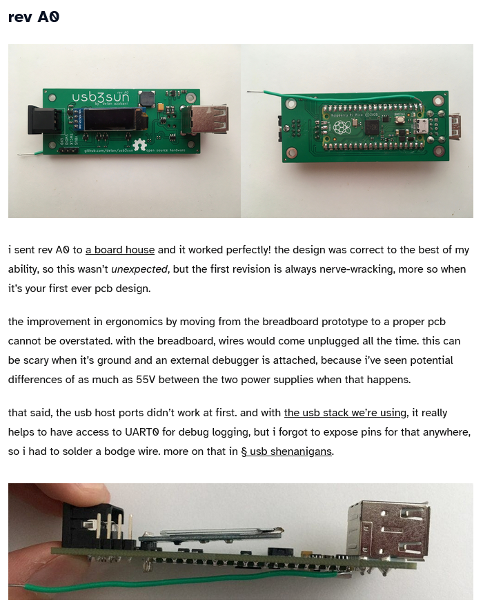
![“ariashark also suggested i add some led indicators to check the state of the two input power supplies, independent of whether the firmware is running. i have two opinions about leds, which are closely related: most leds on consumer electronics are too bright [and] blue leds are the spawn of satan (derogatory)”](/posts/attachments/1daea606-4cbd-48c5-8db6-7cf57c068b1d/image.png)
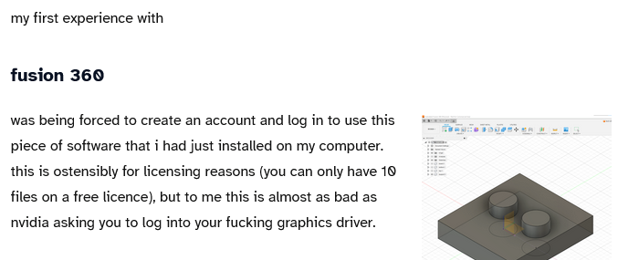
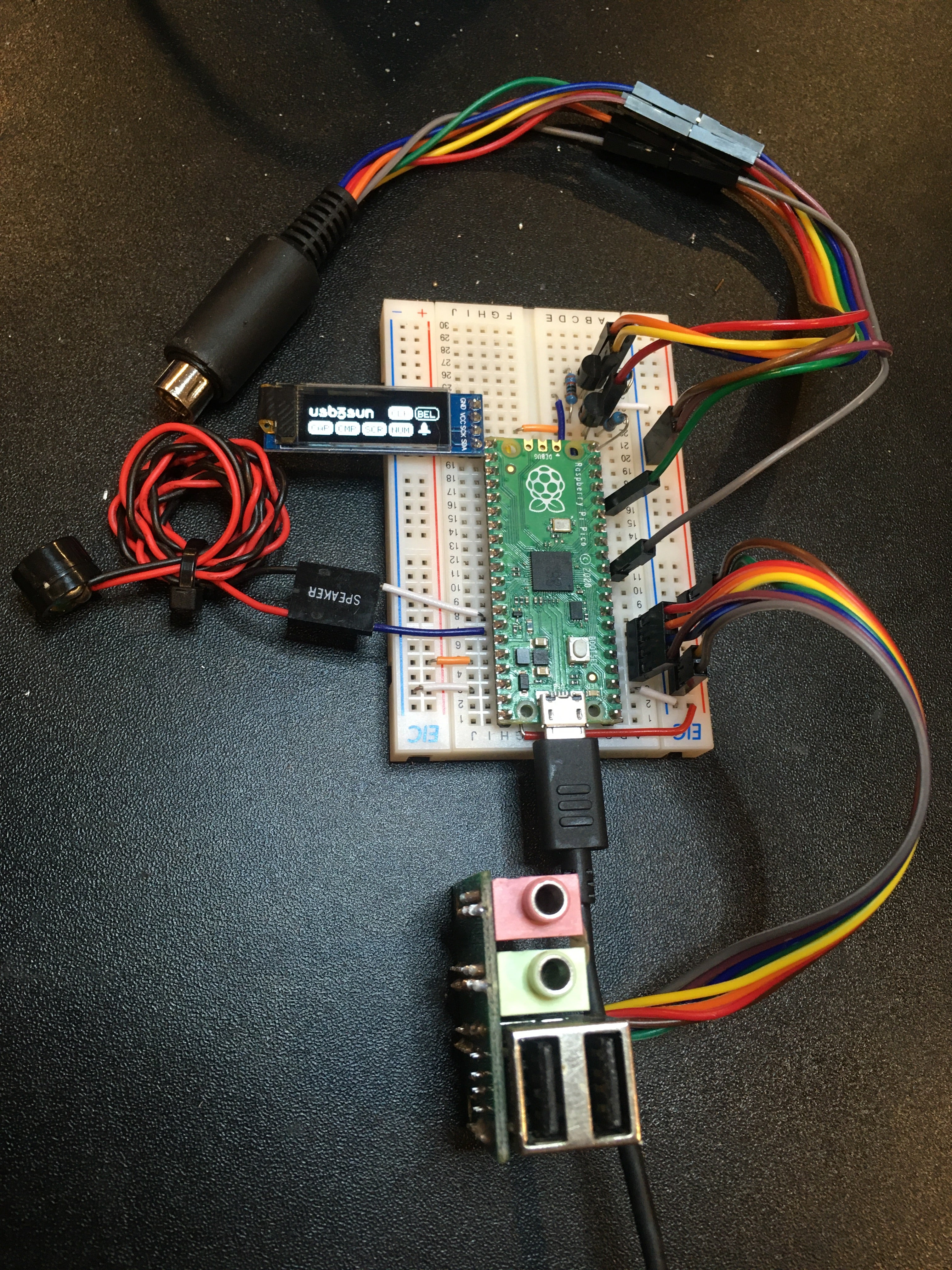
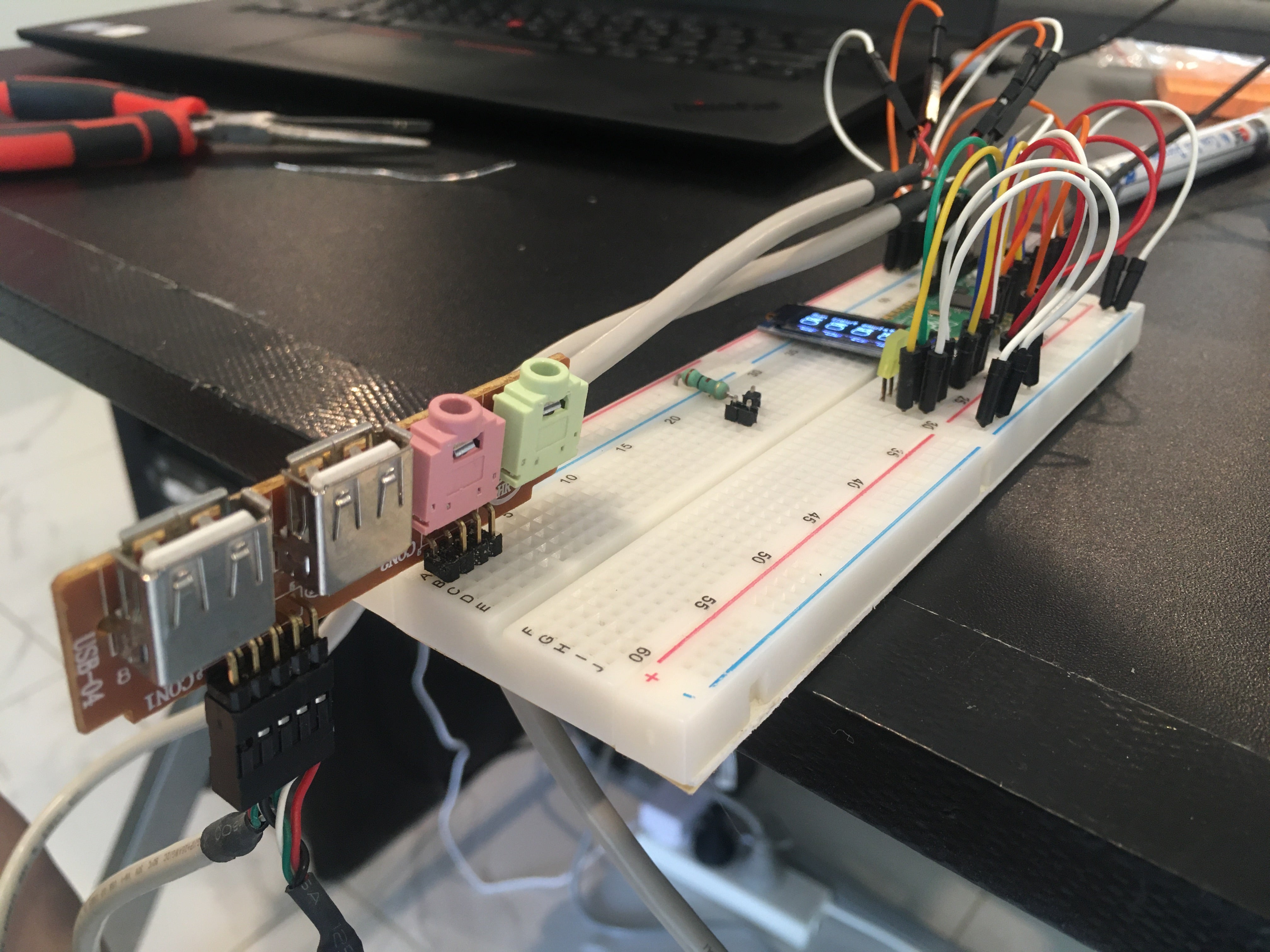
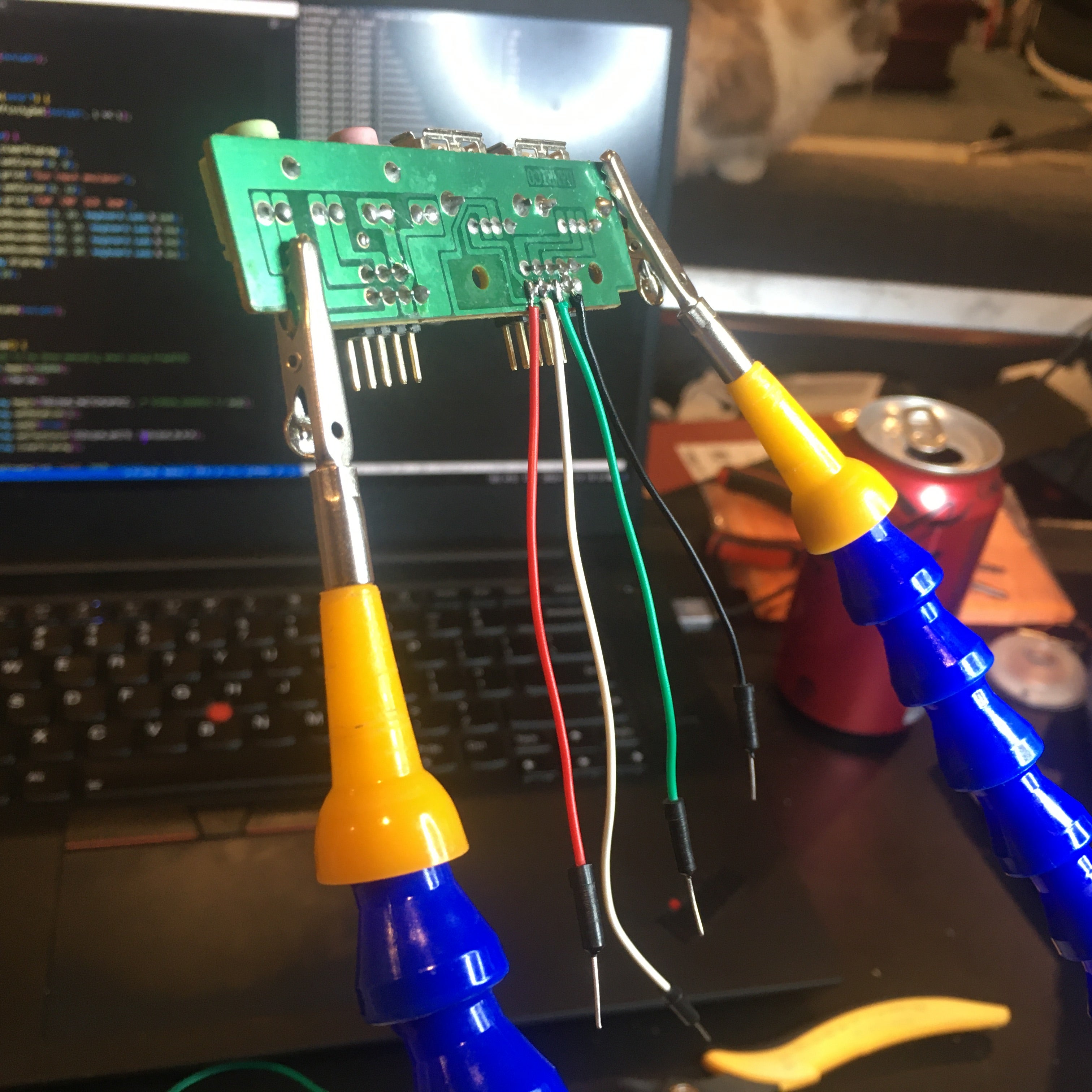
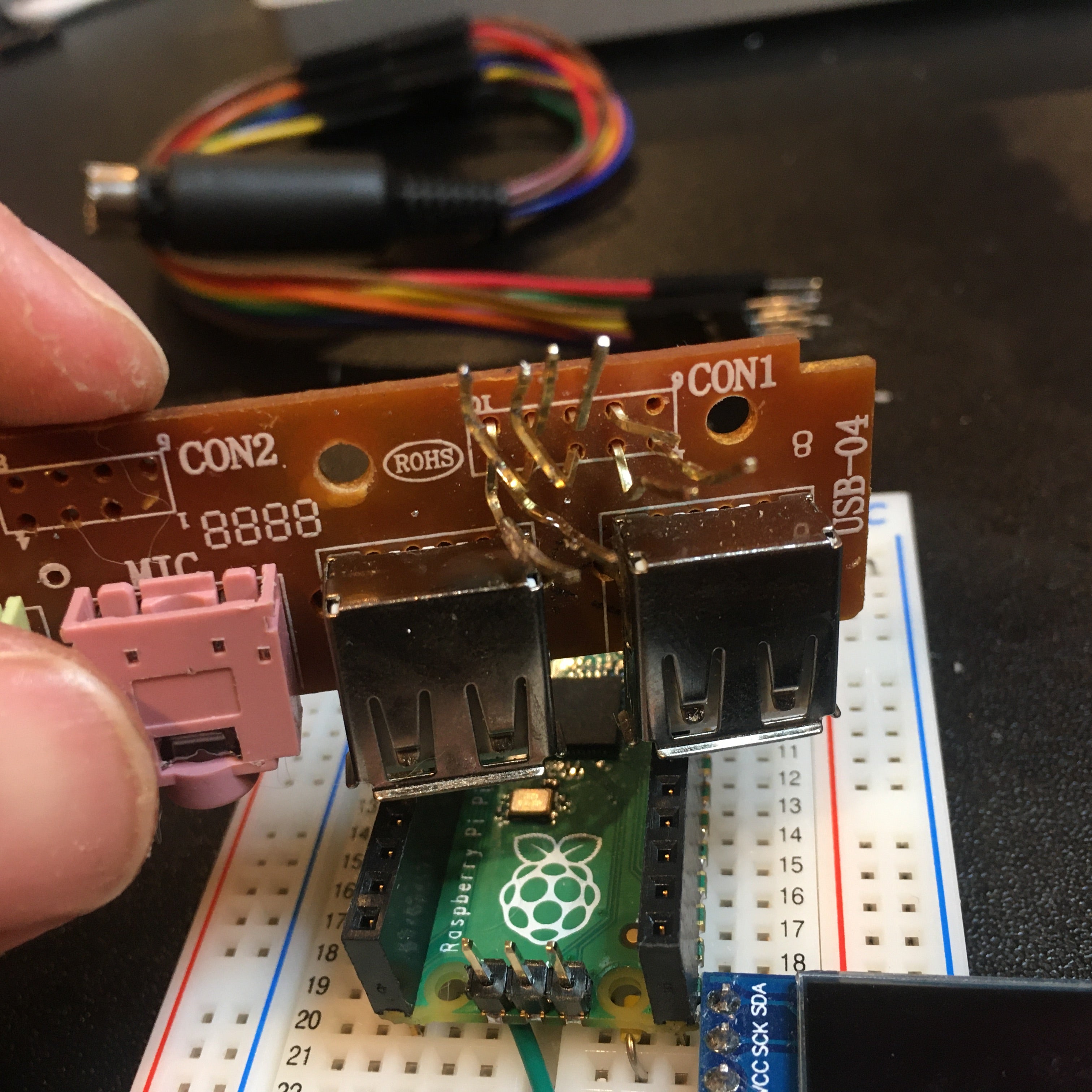
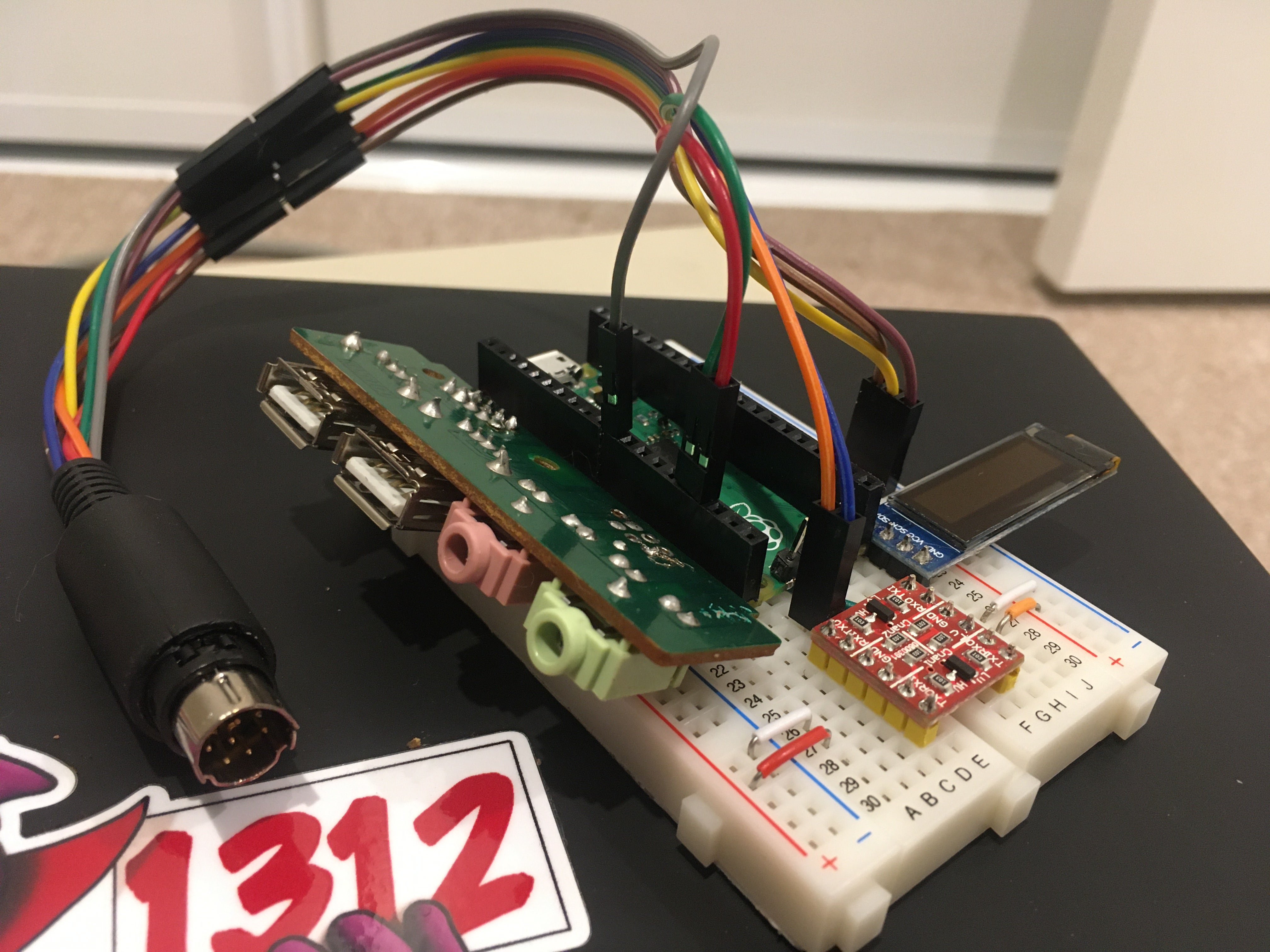
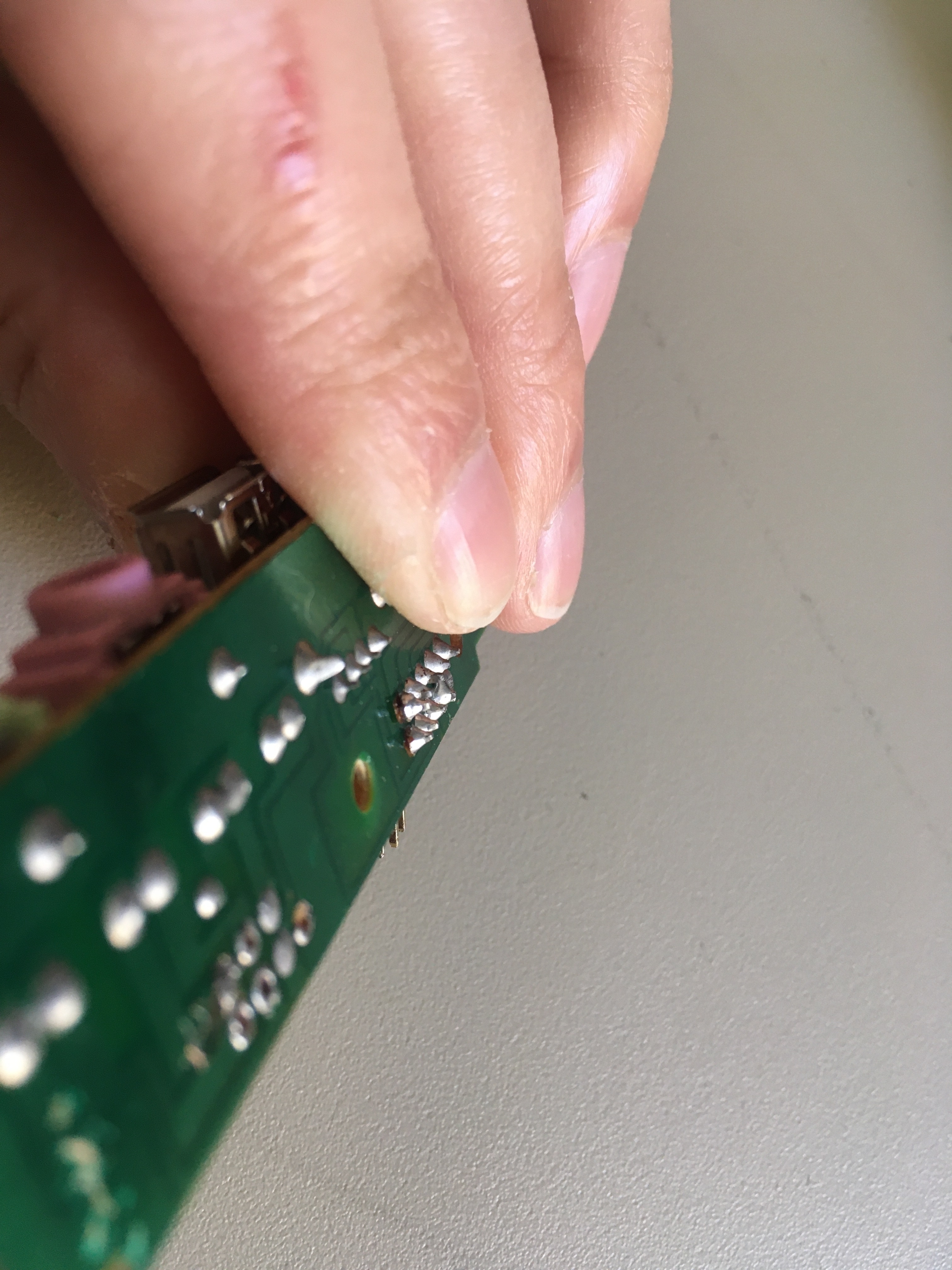
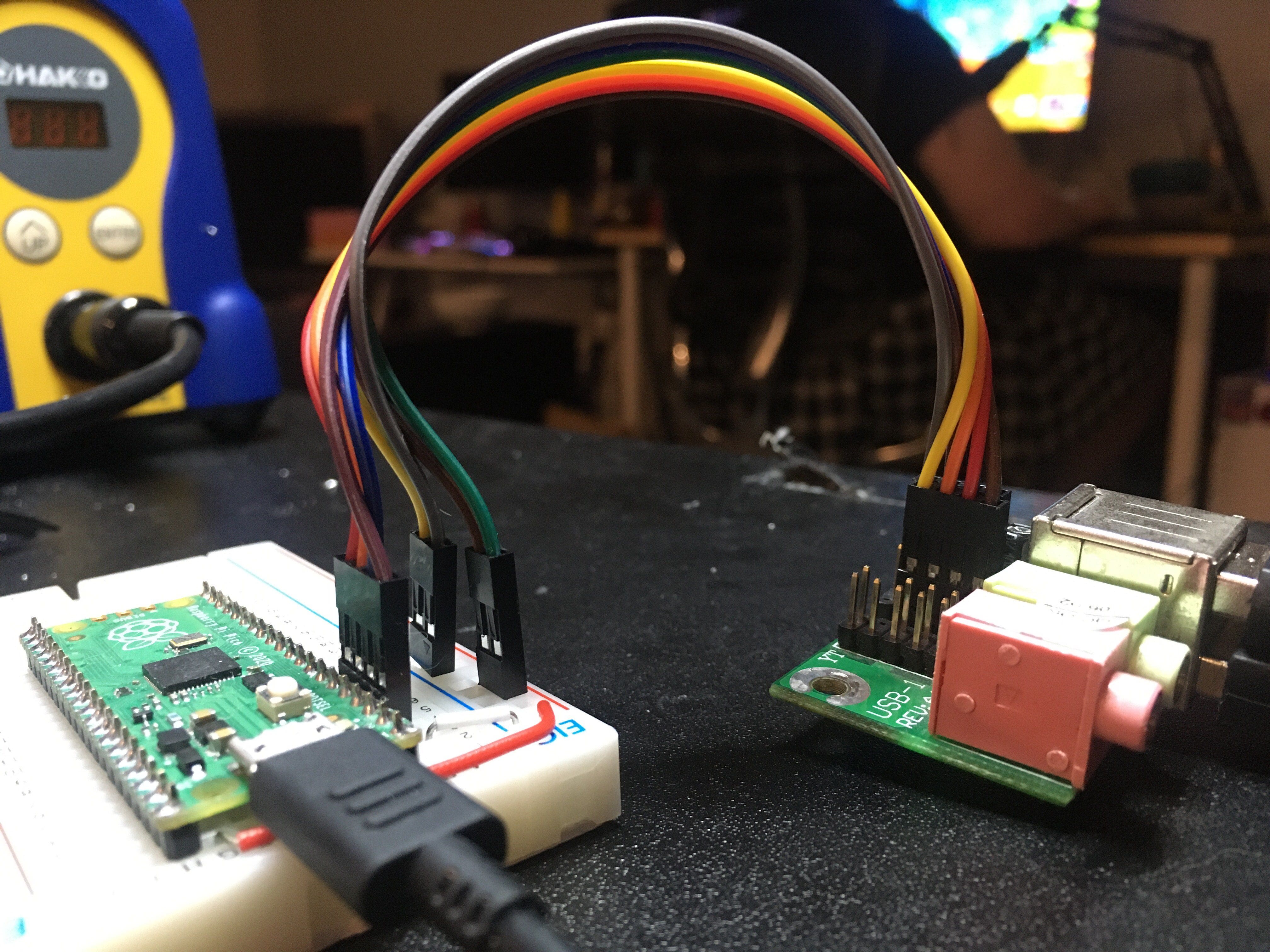
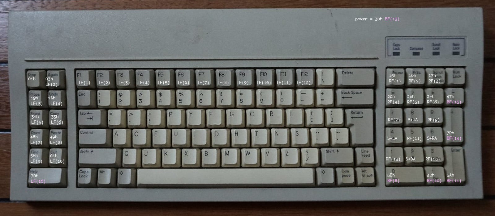
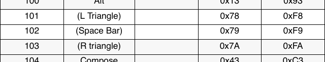
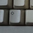


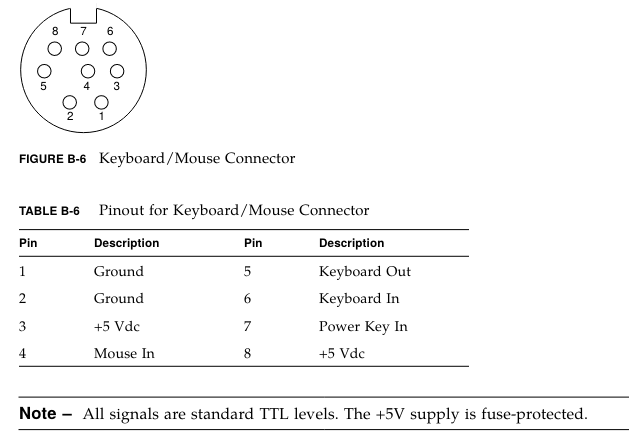

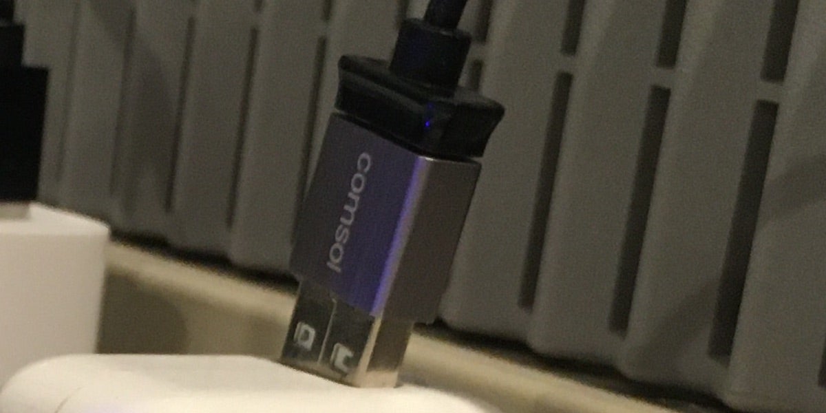
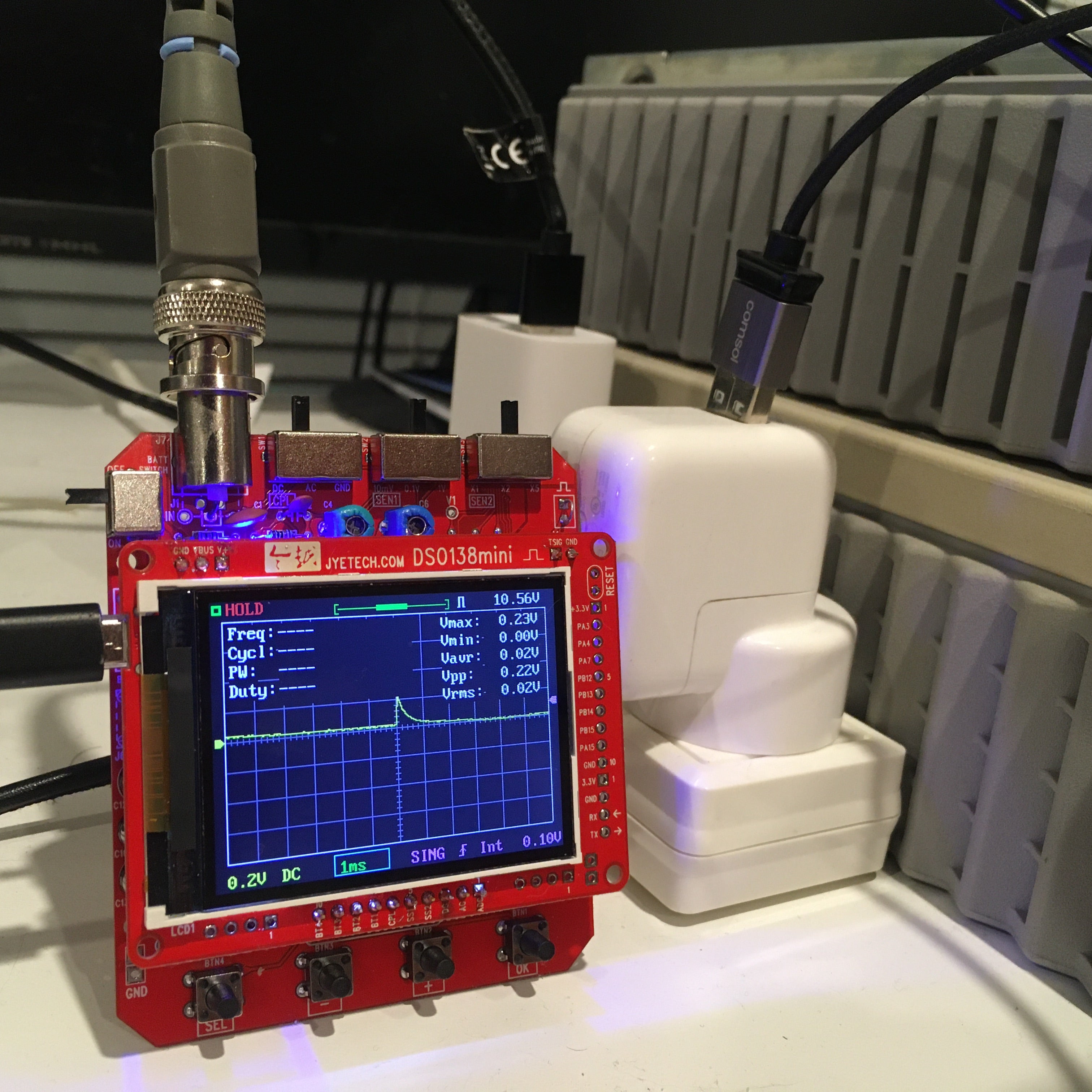
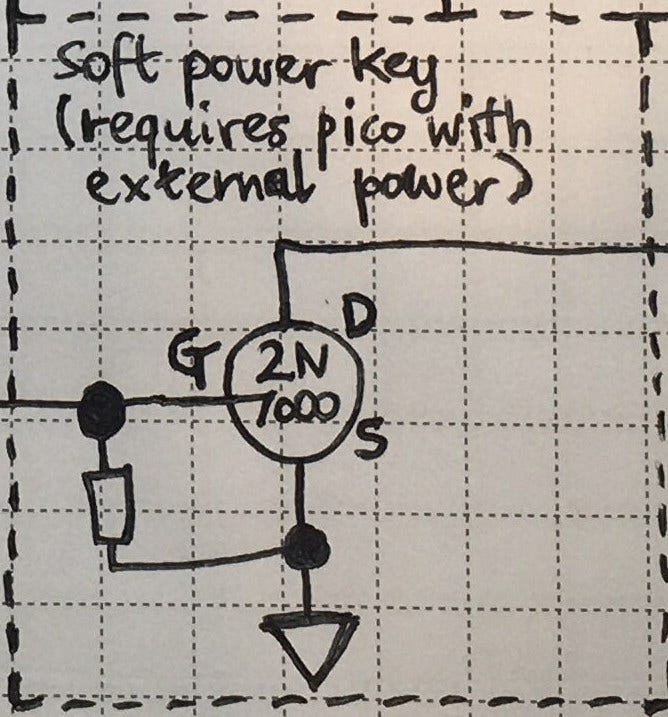
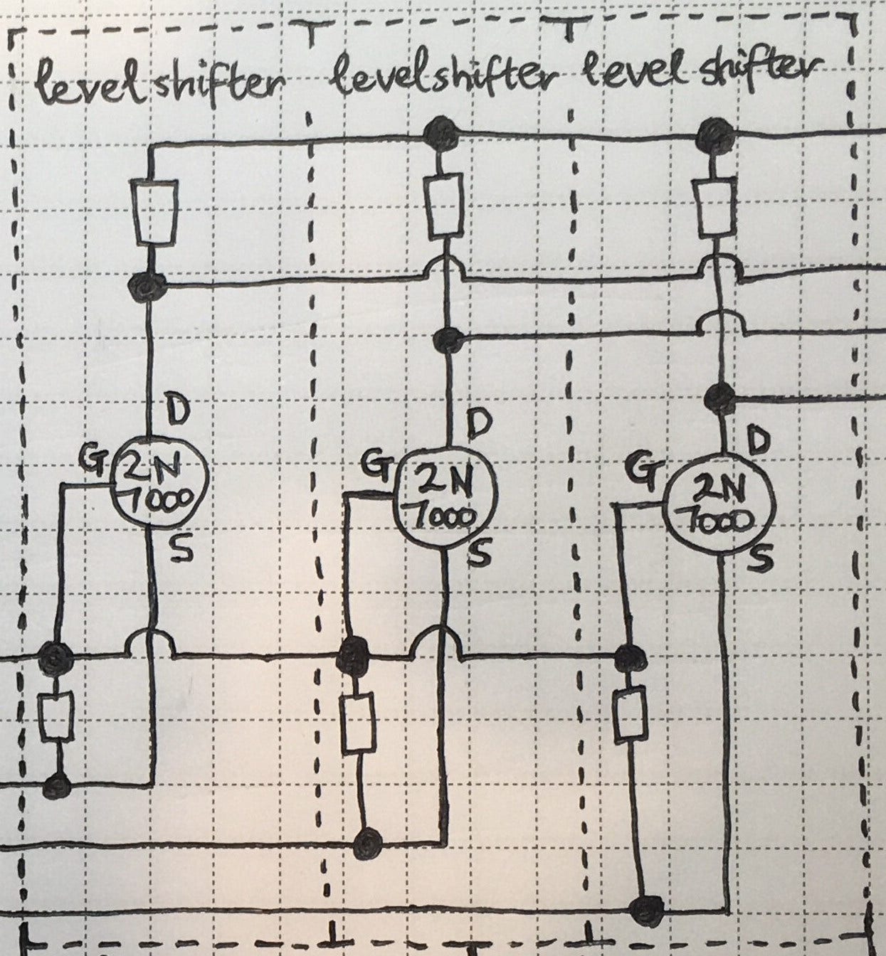
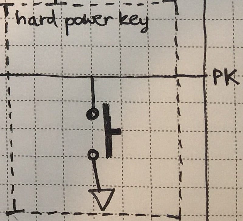
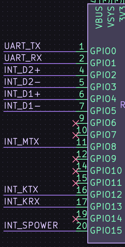
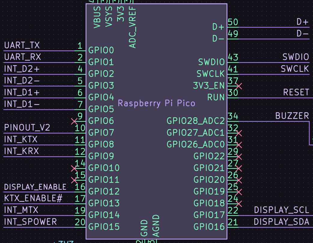