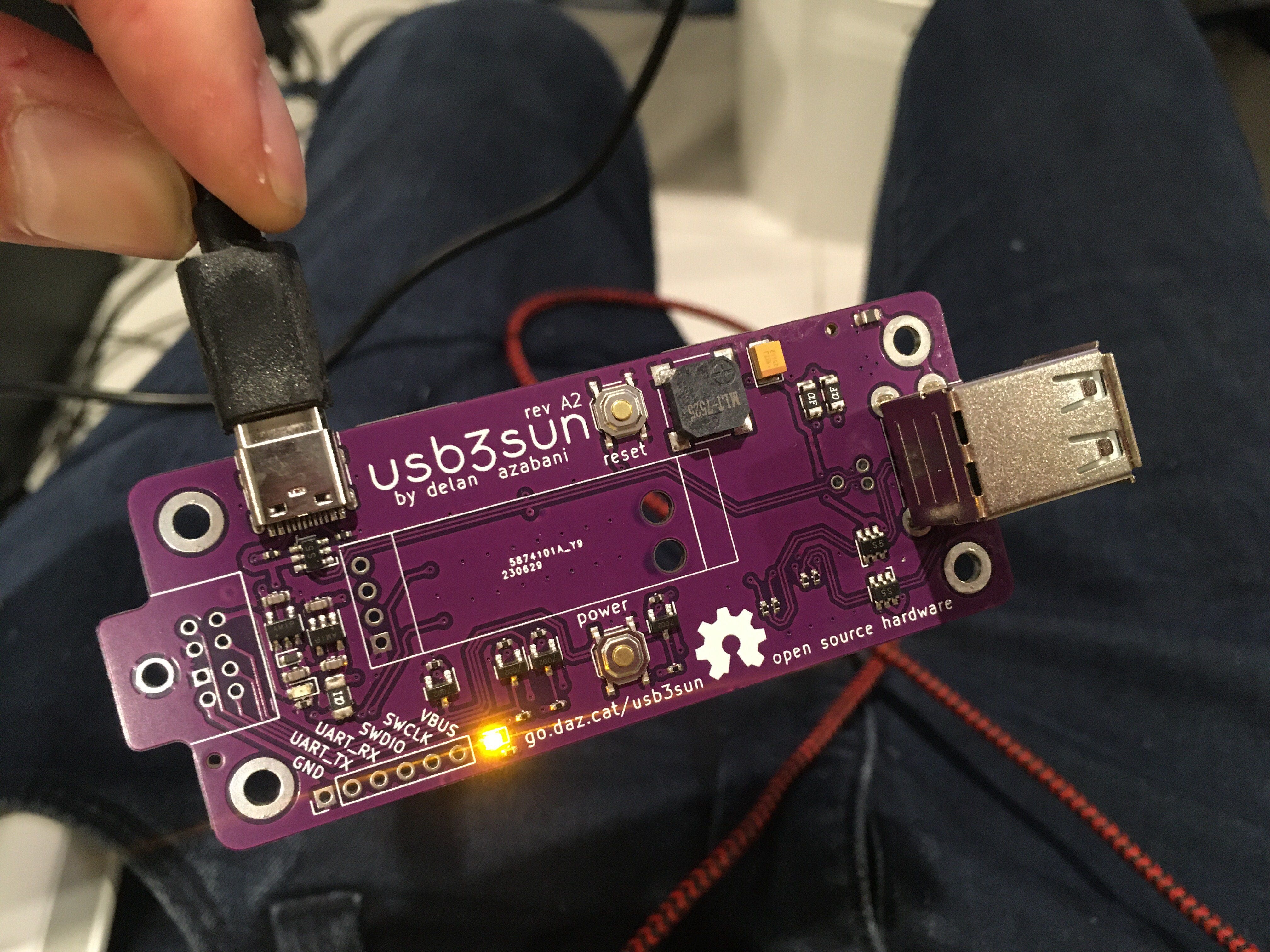
usb3sun rev A2, now with easy firmware updates!
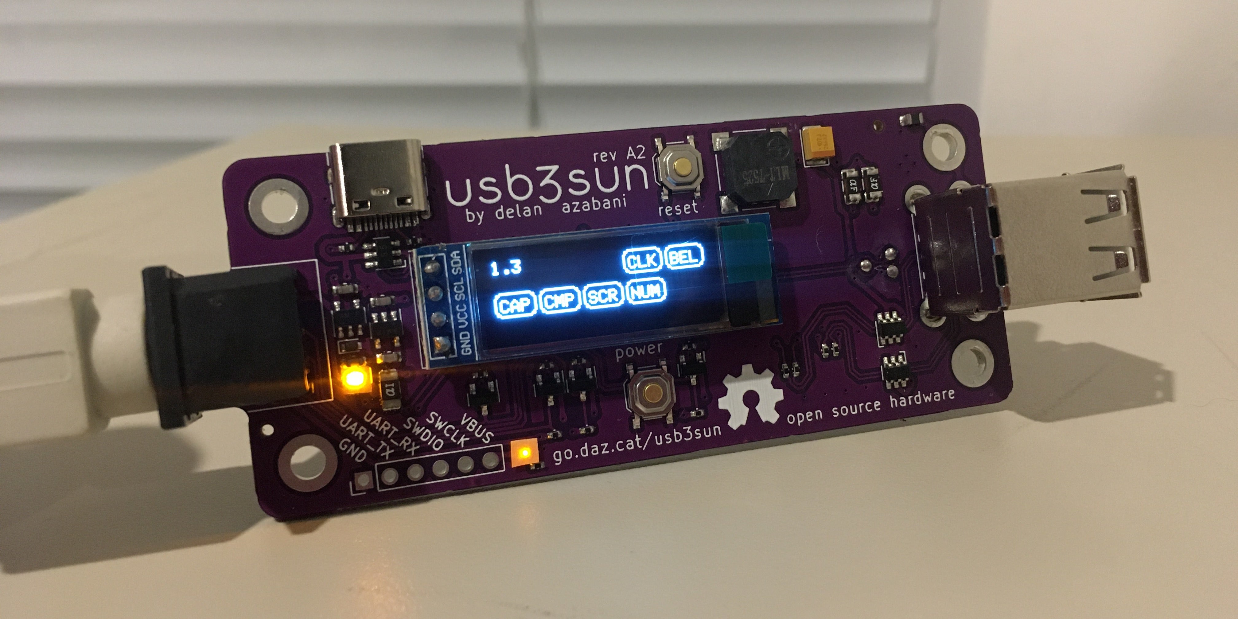
SPARCstations have a unique serial-like interface for keyboard and mouse input, using a single 8-pin mini-din port. usb3sun allows you to use an ordinary USB keyboard and mouse with your sun workstation, and now rev A2 is available on tindie!
the big changes since rev A1 are
- there’s now a proper user guide
- a new usb-c port makes firmware updates much easier
- a new main polyfuse to better protect the adapter as a whole
- the led indicators are still too bright but less than before
this is the third part in a series!
- the breadboard prototype
- rev A0 and rev A1
- rev A2 (you are here)
rev A1 was a huge success, as far as i’m concerned. i didn’t expect to sell more than a couple, and yet here we are! but for our next run, we had a few problems to solve.
- user guide
- routing the pico’s usb port
- adding the new usb-c port
- other changes
- does it work?
- next steps
every device needs a
user guide
, and it was fun writing one for usb3sun.
all of the firmware features and ui elements are documented there, plus detailed guides to setting up the adapter and updating the firmware, and even some of the electrical and thermal characteristics.
i drew the diagram on the User.1 layer in the pcb editor, which made it easy to get the dimensions right. hopefully that will also make it easy enough to keep the diagram up to date.
the guide has cppreference-style version annotations, so it can also be used for rev A0 and rev A1 and firmware versions older than 1.2.
through the magic of stargirl’s kicanvas, there are even links to view the schematics and pcb layouts for each revision in your browser! look i’ll show you!
| rev A0 | rev A1 | rev A2 | |
|---|---|---|---|
| schematic | rendered (source) | rendered (source) | rendered (source) |
| pcb layout | rendered (source) | rendered (source) | rendered (source) |
| display module support | source | source |
routing the pico’s usb port
was a little tricky.
the raspberry pi pico has a micro-usb port that can be used to flash the firmware without any special software, and exposes a cdc serial device for non-usb-related debug logging. but this port becomes physically inaccessible once the pico is soldered onto our adapter.
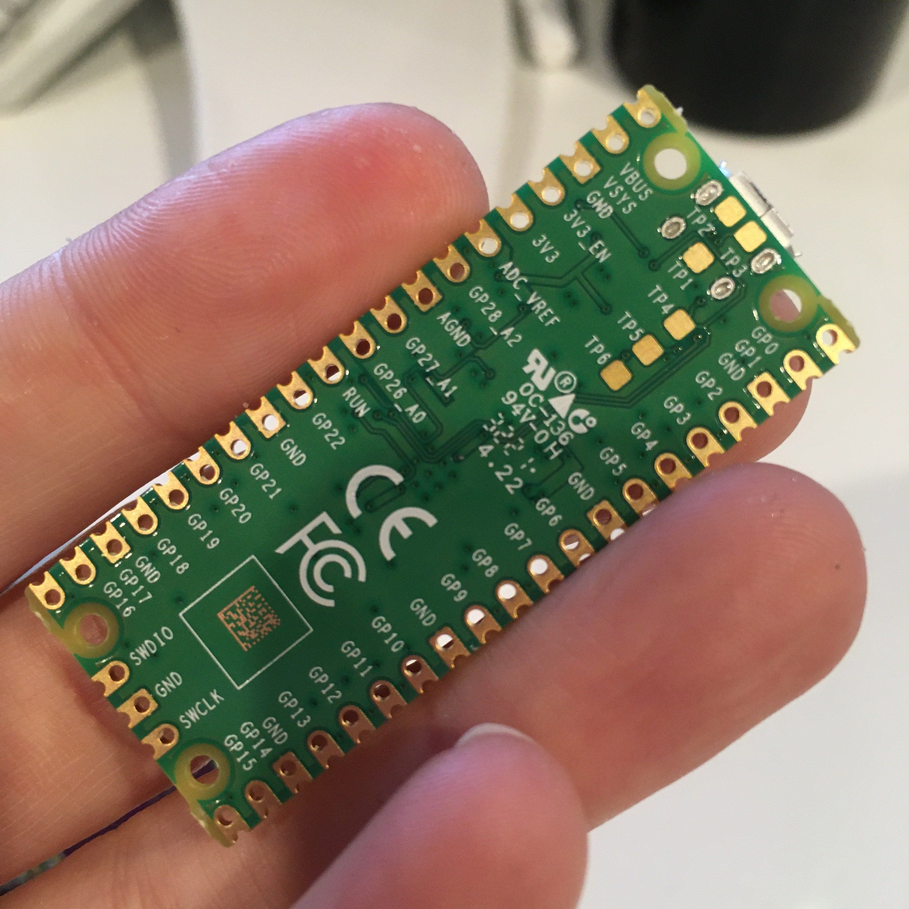
the only other way we can get to it, aside from “inlining” the rp2040 and everything it needs into our design, is the three test points on the underside. the pico is already touching our board, so why not add a few plated through holes that line up with the test points, and fill them with solder to connect?
first we needed to edit the footprint to add the through holes. to avoid making the routing harder than it needed to be, i removed the four holes that were ostensibly for clearance from the micro-usb mounting pins, but in practice weren’t really necessary.
the through holes are circular, unlike the rounded rectangle test points, which is easier for my board house to manufacture. they are also somewhat smaller, which i’m hoping will reduce the chance of defects if the pico is placed slightly offset or on an angle.
that said, we still want to keep anything conductive out of the full area of the test points, plus a bit more for tolerance, and this is where i ran into some kicad limitations. there doesn’t seem to be a way to give holes a custom clearance shape and size. and if we add keepout areas over each through hole that
- forbid tracks and pads, then we can’t connect to the holes, and they will trigger drc errors
- allow tracks and pads, then tracks and pads in other nets will only be kept out of the circular clearances of the holes
fortunately we could still forbid vias and copper fill, and it wasn’t too hard to manually keep traces and pads out of the keepout areas. it was definitely worth doing so though, because solder mask is not intended to be used as insulation.
@ariashark suggested i provide a fallback mechanism to route the usb port to gpio pins, by bridging a pair of solder jumpers. that way, if our plated-holes-over-test-pads strat didn’t work out, we could repurpose the usb-c connector as a third host port.
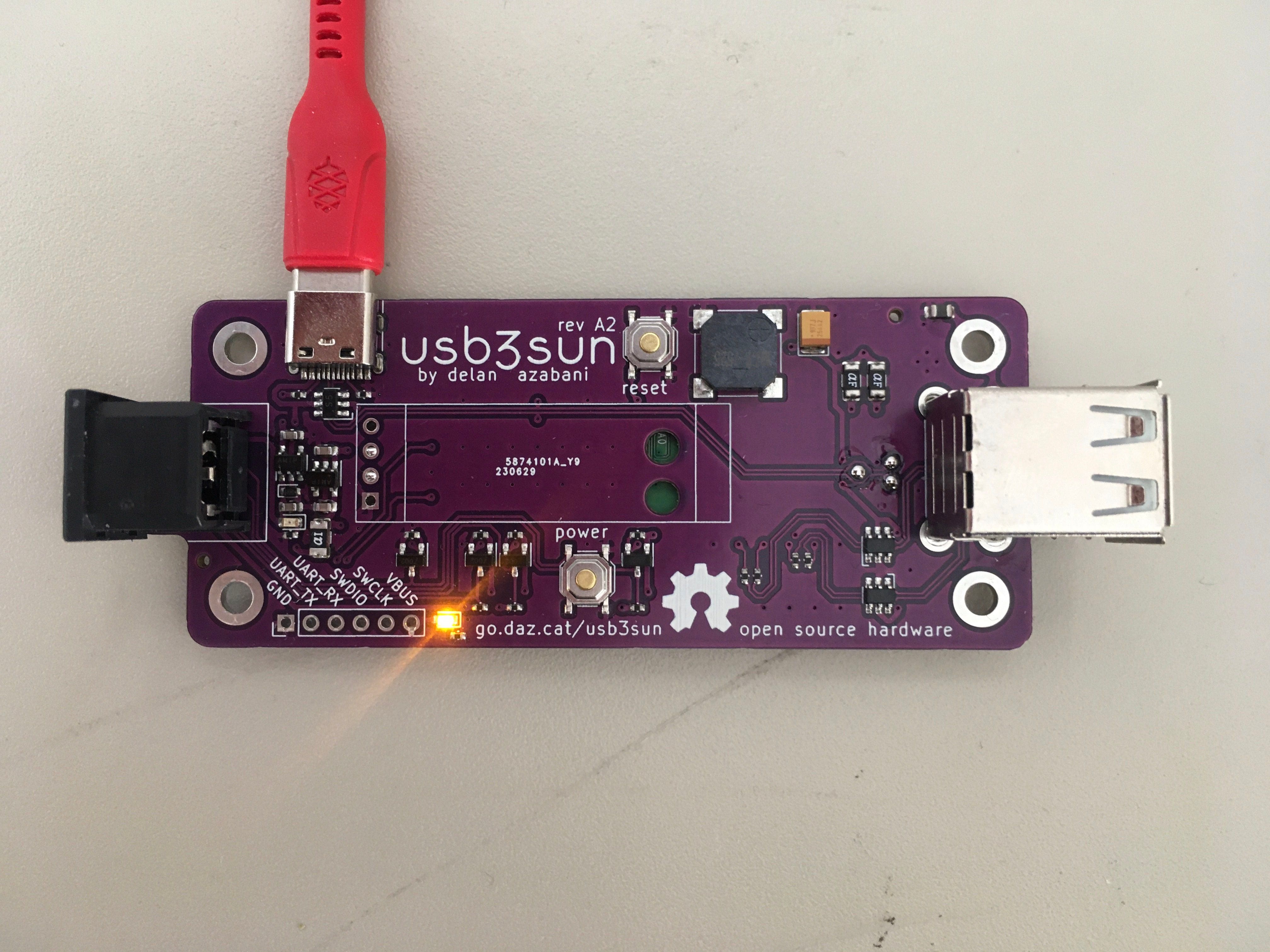
adding the new usb-c port
was surprisingly straightforward.
one of the cool things about usb-c is that there’s a standard way to request up to 3A without any digital logic. this excellent post by arya voronova explains that with just two 5k1Ω resistors, your device may be granted more than just the “default” usb power, up to 1A5 or even 3A, and you can easily check which limit you were granted with a 3V3 adc!
i was careful to ensure i added two 5k1Ω resistors wired on separate nets, to avoid only getting power when plugged in one way, or no power at all with a fancy emarked cable.
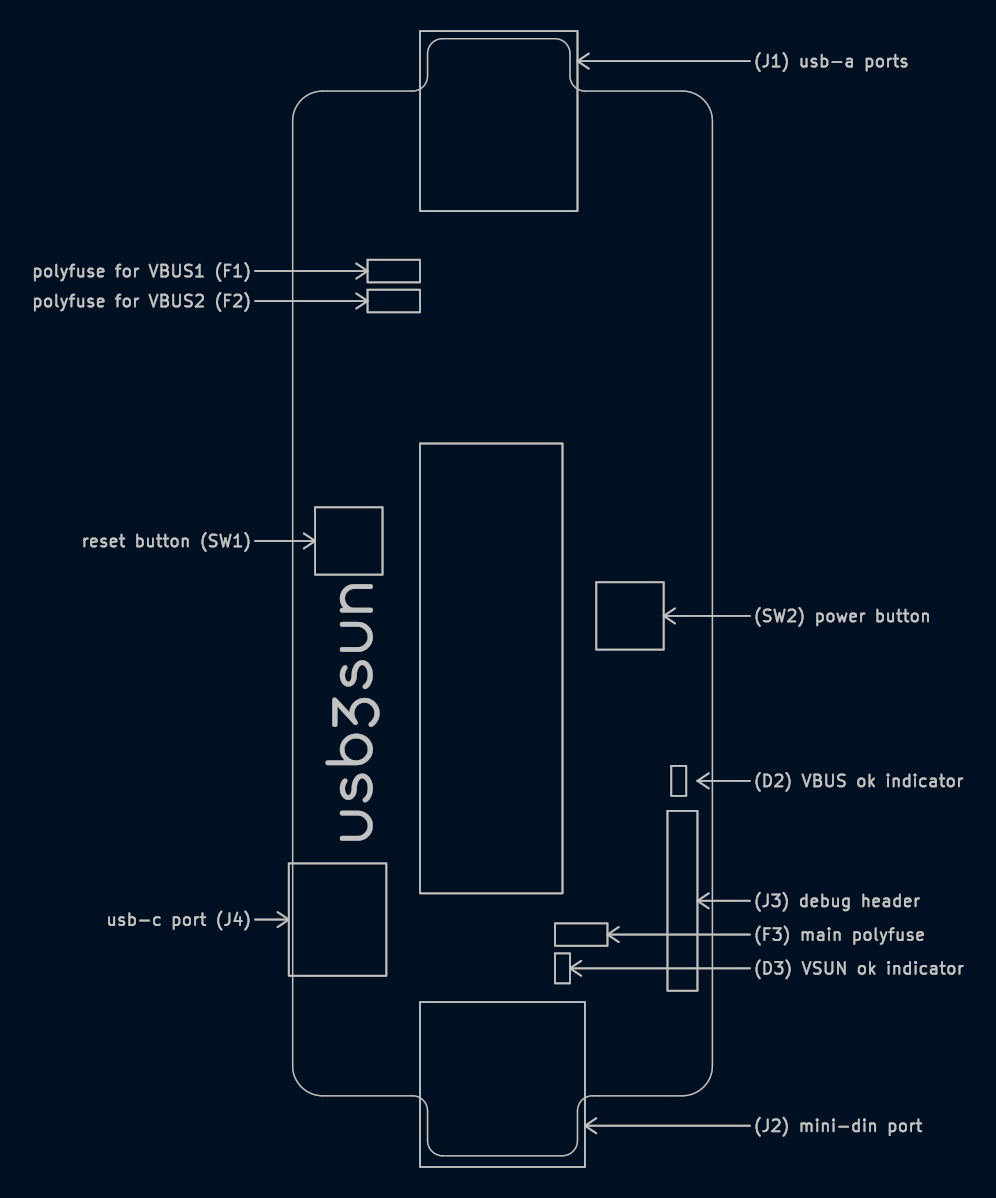
other changes
@ariashark recommended adding a main polyfuse after the power supply switches (ideal diodes), to protect the adapter as a whole under more fault conditions. previously we only had polyfuses in front of the downstream usb ports, so there was still a risk of damaging the adapter if some other part of the circuit was shorted.
i changed the led resistors from 200Ω to 1KΩ, reducing the luminous intensity from ~80% down to ~10% relative to 20mA. i figured 10% would be good enough and i didn’t want to go too far, because then the on state may be mistaken for a malfunction like the ones we’ll cover later in this post.
last and also least, i changed the tactile switches from TS-1187A-C-H-B to its sibling TS-1187A-B-A-B. i picked the former because i liked the heavier actuation force, and i thought the longer shaft would be necessary to reach the outside of a hypothetical future enclosure, which may not even be the case. but the latter is a basic part at jlcpcb, which saves a few bucks per run.
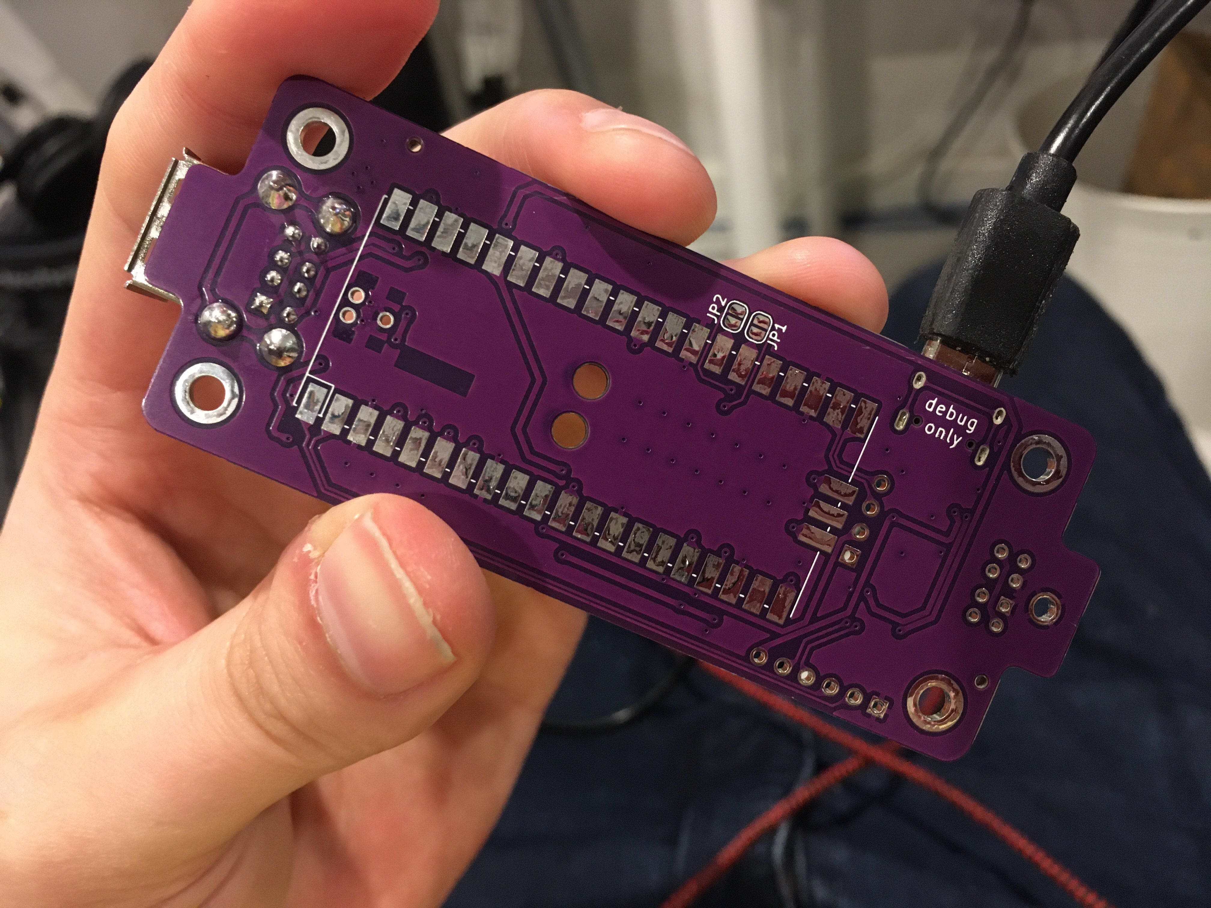
it works!
even the new usb-c port! but there are some minor issues.
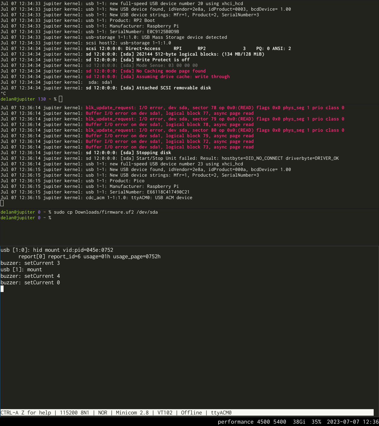
right from top to bottom: enumeration of bootsel mass storage device, enumeration of cdc acm device after flashing, flashing via the bootsel device, debug logging via minicom
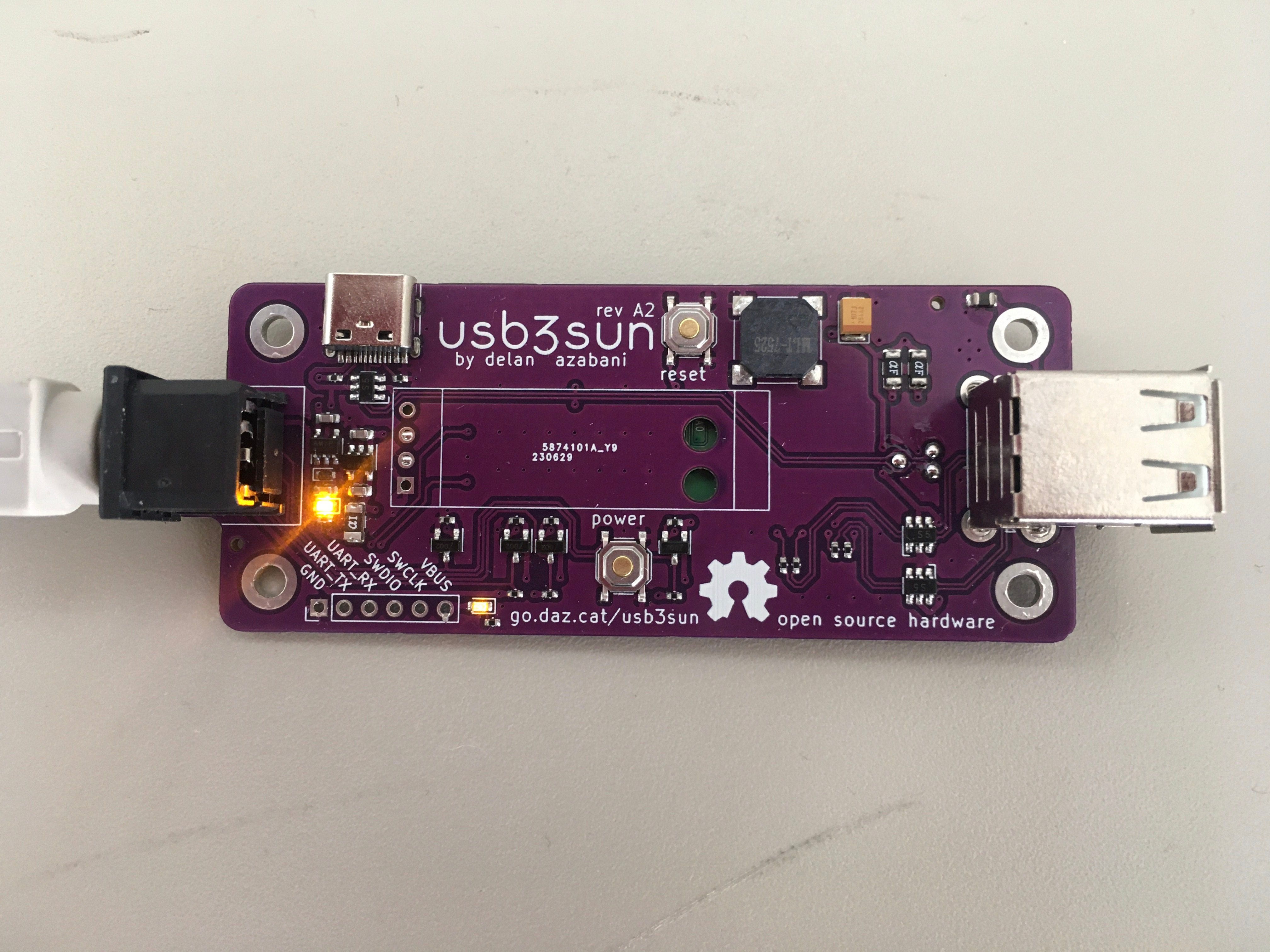
first of all, the led indicators are still too bright! ain’t modern leds amazing?
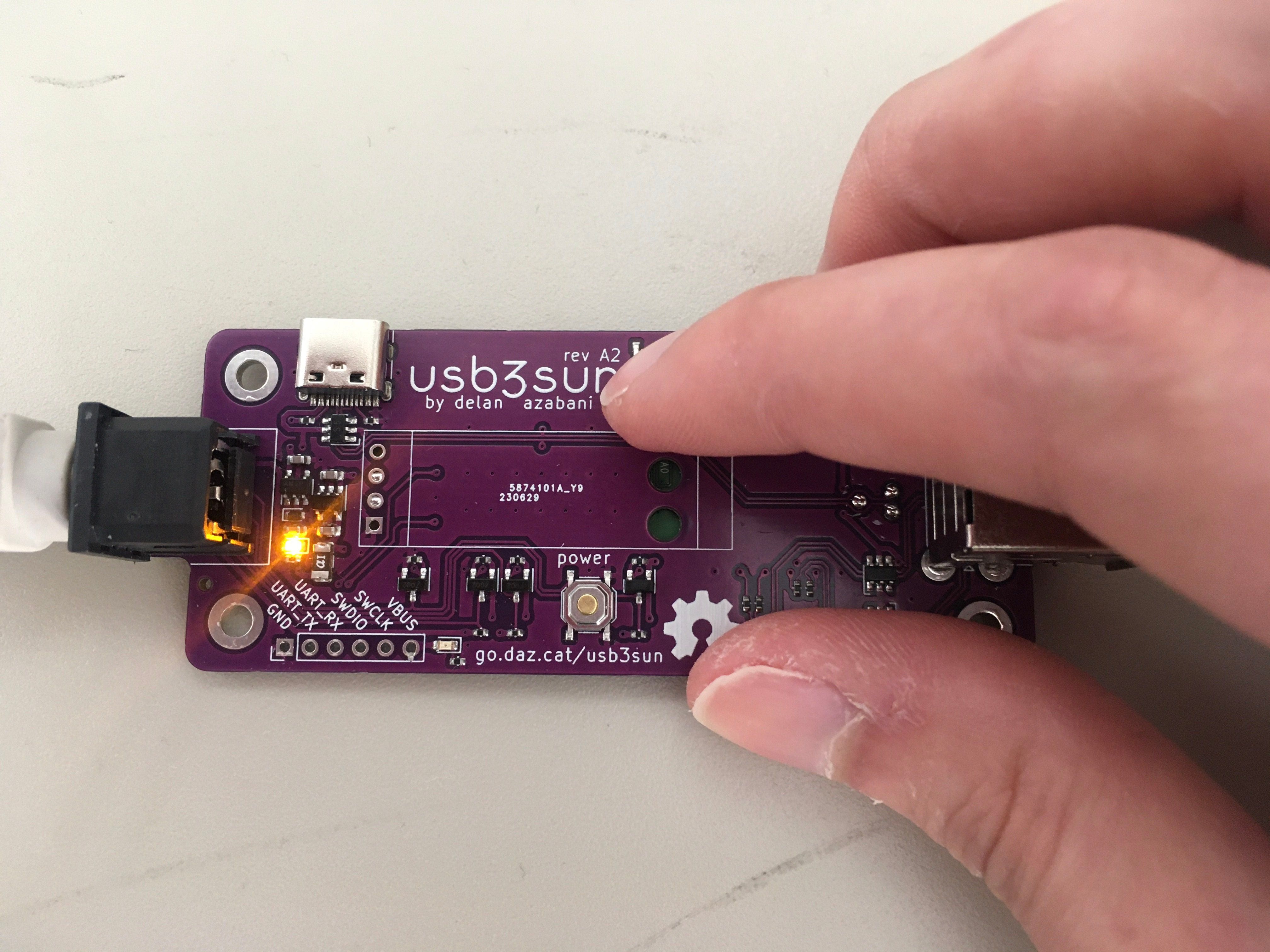
there’s also one problem new to rev A2. when the adapter is powered by VSUN, the VBUS indicator dimly lights up soon after, except while the reset button is being pressed.
probing the led’s anode with an oscilloscope, we saw a steady 2V2 or so while the VSUN indicator was dimly lit. checking resistance between VSUN, VBUS, 3V3, and GND showed normal values mostly between 574K and 748K, with VBUS ↔ VSUN being around 3M in both directions, so @ariashark and i started looking for other things that changed in rev A2.
my first idea was that our VBUS used to be tied to the pico’s VBUS pin, but since we were powering the pico via its VSYS pin anyway, that was unnecessary, so i disconnected it in rev A2. but jumping the pin onto VBUS didn’t change anything.
over time, we started to doubt that the current was being conducted onto the net, and started worrying that the current was being induced from elsewhere. after all, i had crammed all of the power supply and usb-c circuitry together quite aggressively… maybe too aggressively?
so i asked the fediverse. after realising i needed to repost it under some relevant tags, we got an answer in under an hour:
https://kolektiva.social/@babouille@piaille.fr/110721497635863990
the root cause was indeed D+ leaking through the esd diode array. the pico is running, so its D+ line is pulled up to 3V3 to show that it’s a full speed device. but there’s no voltage on our VBUS, which the esd array is using as a reference, so that 2V85 flows up the steering diode onto VBUS, which becomes 2V15 after the diode drop. this is below the tvs diode’s breakdown voltage, so it stays on VBUS without getting shunted to ground.
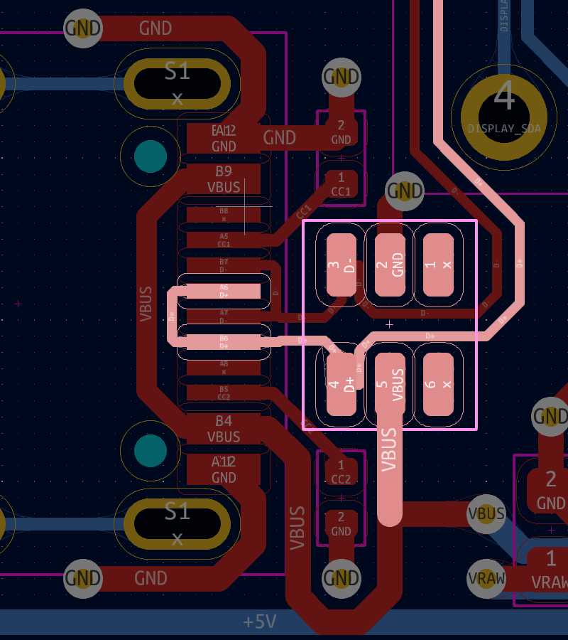
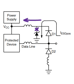
2V15 is enough to push about 150µA through our led and its resistor, lighting it up ever so slightly. but since there’s already 5V from VSUN on the other side of our ideal diode, it should be blocked from powering anything else. and since VBUS will always be powered while using the upstream usb port, it shouldn’t affect usb signal integrity.
next steps
our next revision will decrease the brightness of those led indicators even further, and fix the bug where the VBUS indicator can erroneously light up. we may also fix the bug where the VSUN indicator can erroneously light up while resetting the adapter.
the usb-c port is currently marked “debug only” because it’s currently only used for firmware updates and debug logging, but in theory it could be used as a third host port with only firmware changes, so we may be able to remove that from the silkscreen.
otherwise the design is fairly complete. what i’m far more excited about is implementing a macro feature, to make it easier to reprogram your hostid. if you’re as excited about that as i am, hopefully that will be a lot more accessible to you, now that firmware updates are as easy as dragging and dropping a uf2 file onto a usb drive!
if you think you’ll find usb3sun useful, consider buying one on tindie! there are four left in this initial run, but after those, we’ll order and assemble more.
did you love this? hate this? have any questions or comments? please let me know in the comments below, or on mastodon or twitter!