usb3sun rev B0, a usb input adapter for sun workstations
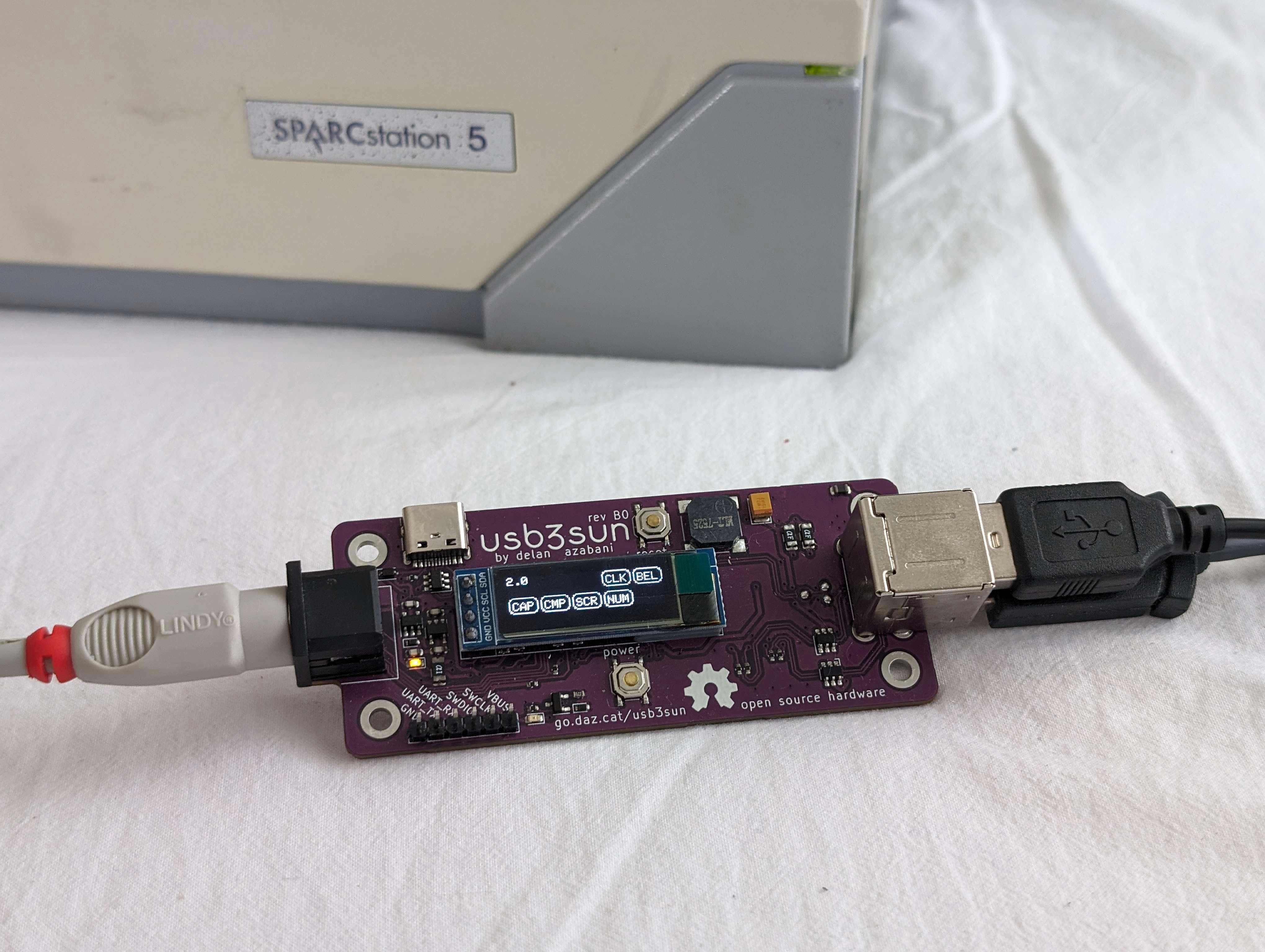
SPARCstations have a unique serial-like interface for keyboard and mouse input, using a single 8-pin mini-din port. usb3sun allows you to use an ordinary usb keyboard and mouse with your sun workstation, and now rev B0 is available on tindie!
this revision has been all about polish, with improvements to reliability and debuggability. we’ve fixed bugs where resetting the adapter drops you into an ok prompt (#2) and (rarely) hangs until power cycled (#11), and you can now use the debug uart without disabling the sun keyboard interface (#10).
we’ve also added a fun new debug cli, allowing you to send keyboard and mouse input to the workstation via the (now always accessible) debug uart. while it doesn’t yet support all possible inputs, you can already use this as a limited form of automation!
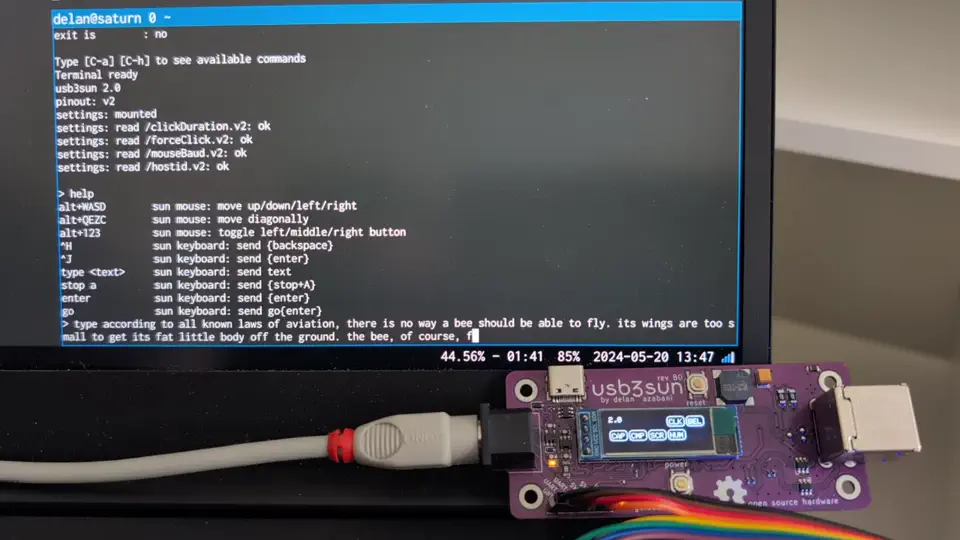
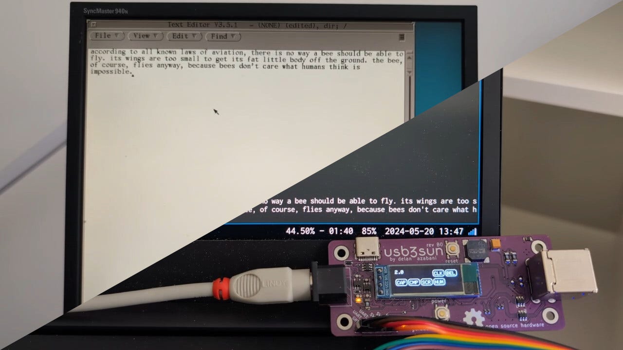 ▶
▶
since we still have a few rev A3 adapters left in stock, those are now 20 USD off on tindie. rev A3 is affected by the reset errata, and lacks support for debugging with the sun keyboard interface enabled, but for most people it should still be more than usable.
print your own enclosure
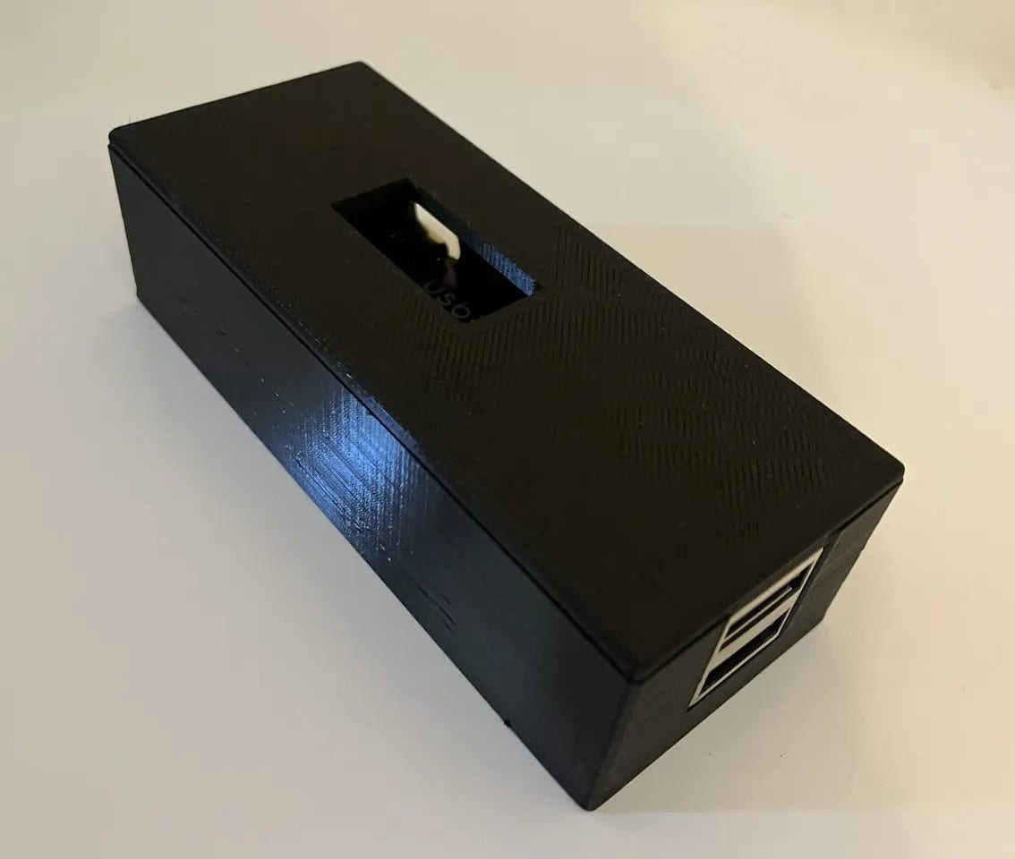
legodude designed a 3d-printed enclosure for the usb3sun! it should be compatible with all boards rev A1 and newer, though it doesn’t currently provide access to the debug header or led indicators.
break preventer (#2)
when resetting older adapters, the workstation would drop you into an ok prompt. this pauses the running operating system (or program) until you type “go” to continue, but programs don’t always handle that well. for example, on solaris running X11, the screen contents may get mangled and it may even kernel panic if booted over nfs.
sun workstations are designed to pause when the keyboard is disconnected and reconnected. they do this by detecting if the keyboard tx line goes from the “break” state to the “idle” state. there are actually only two symbols ever transmitted over a serial line, “mark” (1) and “space” (0), so what are “break” and “idle”?
the receiver (workstation) holds the line in “space” (0) by default, but the sender (keyboard), if present, holds the line in “mark” (1) by default. since every frame starts with a “space” (0), we know that nothing is being sent if there are no spaces. this is known as “idle”.
since an 8N1 serial line also guarantees at least one “mark” (1) every ten symbols, the receiver can infer that nothing is connected if the line is “space” (0) for longer than that. this is known as “break”.
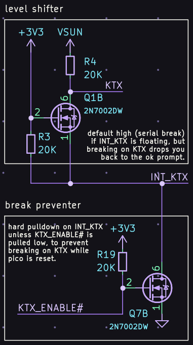
but the workstation also pauses when we reset our adapter, because during reset, INT_KTX is floating, leaving our level shifter to its default state of high, which in sun’s inverted serial logic means “space” (0). this is indistinguishable from a break.
we fixed this by adding a mosfet that pulls INT_KTX low unless the firmware asserts KTX_ENABLE#. during reset, KTX_ENABLE# is deasserted by a pullup resistor.
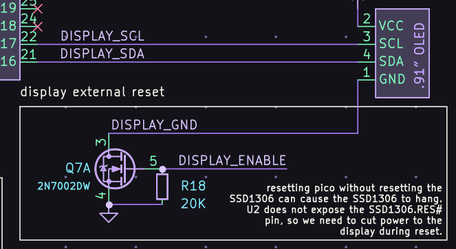
display external reset (#11)
resetting older adapters can also make them hang until power cycled, especially if you mash the reset button several times in quick succession. you’ll know when this happens because the pico’s onboard led indicator will be stuck on.
this happens because the display module malfunctions, holding SDA low so we can’t send anything. while the SSD1306 itself has a reset pin, the 4-pin display modules that we use do not, so there’s no way to reset them when they malfunction.
we fixed this by adding a mosfet that acts as an external reset, disconnecting the display from ground unless the firmware asserts DISPLAY_ENABLE. during reset, DISPLAY_ENABLE is deasserted by a pulldown resistor.
pinout v2 (#10)
for proper debug logging that includes deps like tinyusb and arduino-pico, we need to use our serial debug port (UART_TX and UART_RX). logging over usb cdc is fragile, breaks when stepping through a debugger, and for tinyusb it would also be a chicken-and-egg.
to avoid a chicken-and-egg inside arduino-pico, we need to use a hardware uart specifically, because everything other than the hardware uart module itself, including the other serial modules, expect that they can use debug logging for errors.
we’re already using both hardware uarts for the sun interface — one for the sun keyboard (sunk) and one for the sun mouse (sunm), so we need to move one of those to SerialPIO, a pio-based uart. but some pio resources are already taken up by usb and the buzzer (as of this commit):
- pio0 has 4 sm (state machines) and 32 instructions
- pio1 has 4 sm (state machines) and 32 instructions
- usb tx needs 1/4 sm and 22/32 instructions within one pio unit
- usb rx needs 2/4 sm and 31/32 instructions within one pio unit
- buzzer needs 1/4 sm and 9/32 instructions within one pio unit
- SerialPIO tx needs 1/4 sm and 6/32 instructions within one pio unit
- SerialPIO rx needs 1/4 sm and 7/32 instructions within one pio unit
let’s play the world’s most annoying bin packing game!
the state machines fit easily, e.g. (1+1+1)/4 sm on pio0, (2+1)/4 sm on pio1.
the instructions? not so much. even ignoring the split between pio units, 22+31+9 = 62/64 instructions, which leaves no space for 6 or 7 more, so we need to move the buzzer back to hardware pwm.
now we’re at 22+31 = 53/64 instructions, again ignoring the split, which is enough for 6 or 7 more, but not 6 and 7 more, so we can only move one tx or one rx to pio, not both.
but moving one rx to pio would not be useful for debug logging, so we can only move one tx to pio, not both or just one rx.
uarts operate at a single baud rate in both directions, which is 1200 baud for the sun keyboard, so if we move sunk tx to pio, the debug port would need to run at 1200, not 115200 baud. this is not a problem for the sun mouse, which has no rx, so we need to keep the sun keyboard on a hardware uart while moving the sun mouse to pio.
this gives us 1+2+1 = 4/8 sm and 22+31+6 = 59/64 instructions, which we can split such that pio0 has 1+1 = 2/4 sm and 22+6 = 28/32 instructions, while pio1 has 2/4 sm and 31/32 instructions. so we’re done right?
ahaha no, of course not
in our pcb, the debug port was on UART0, the same hardware uart as the sun keyboard, so we need to move either the debug port or the sun keyboard to UART1.
since the hardware uarts have restrictions on which pins you can use them with, and none of the pins can be used with both uarts, that means both of them were wired to pins only valid for UART0, so we’ll also need to change our pcb.
older versions of adafruit tinyusb, prior to these commits that were completely unrelated to debug logging, only supported debug logging to Serial1 (UART0), so i figured it was preferable to move the sun keyboard to UART1 while keeping the debug port on UART0.
so altogether, here’s what we had to do…
- move the buzzer from pio to hardware pwm
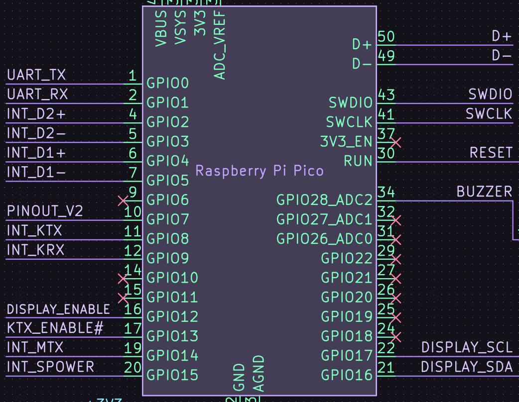
- keep UART_TX and UART_RX on GP0/GP1 (UART0)
- move sun mouse tx from GP8 (UART1) to GP14 (SerialPIO)
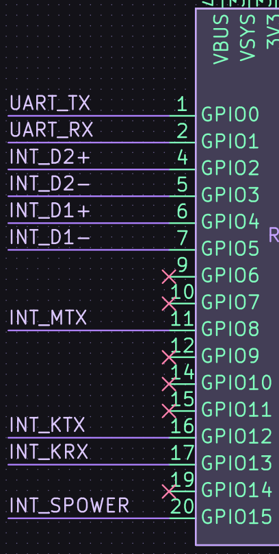
- move sun keyboard tx/rx from GP12/GP13 (UART0) to GP8/GP9 (UART1)
- tie a new PINOUT_V2 pin (GP7) high to let the firmware know that we’re on the new pinout, so the same firmware can be used for both old and new boards
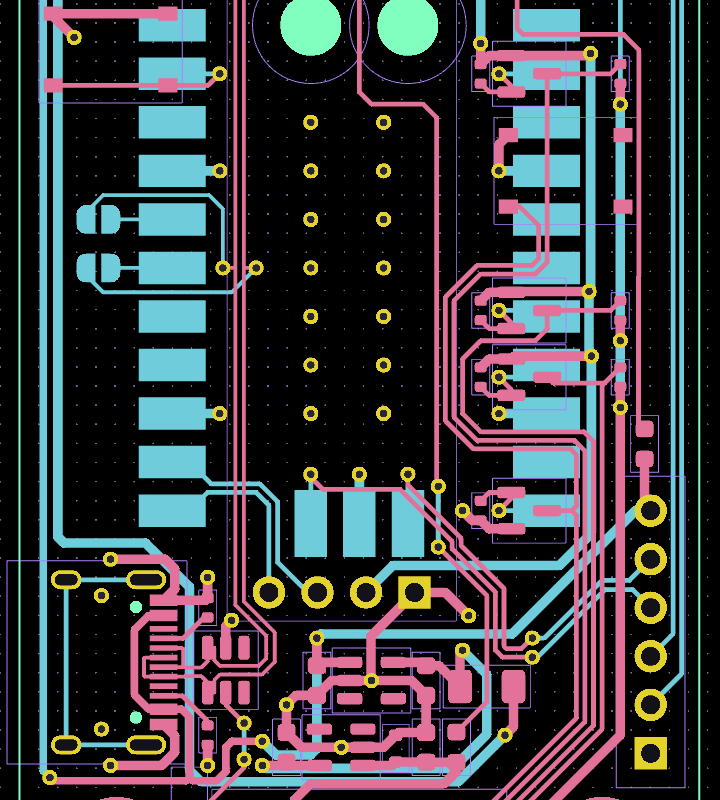
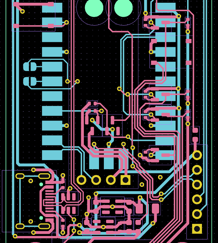
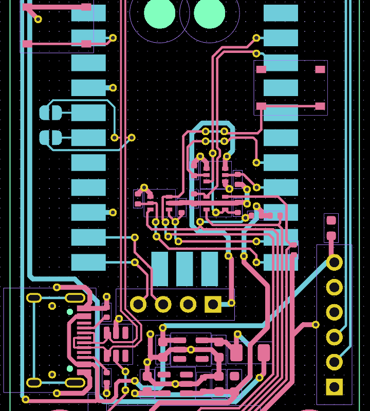
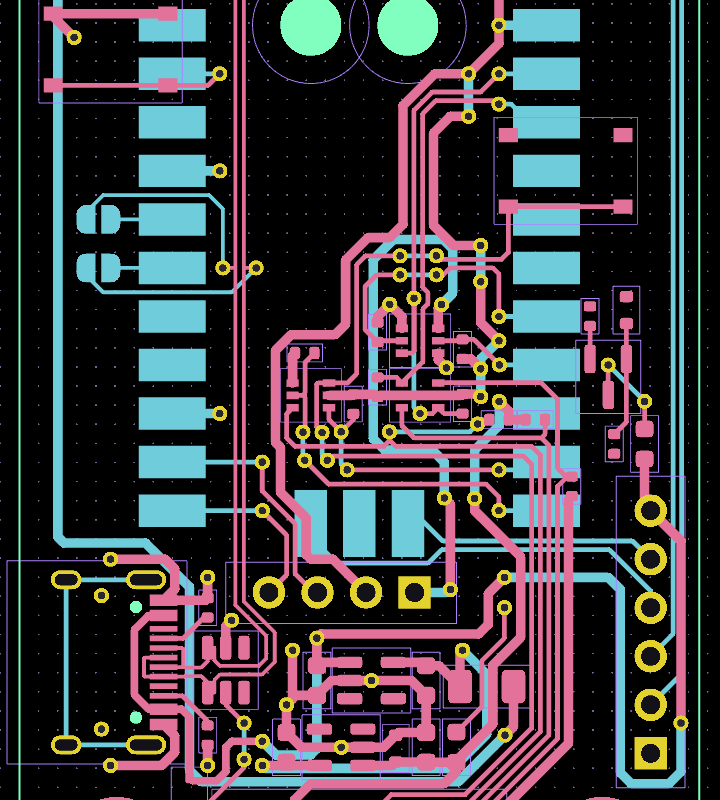
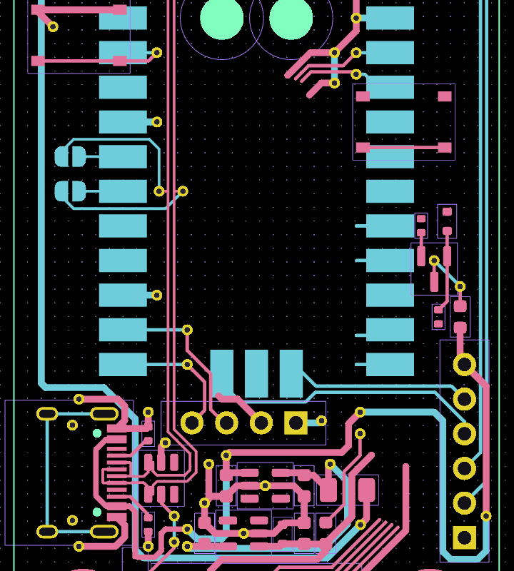
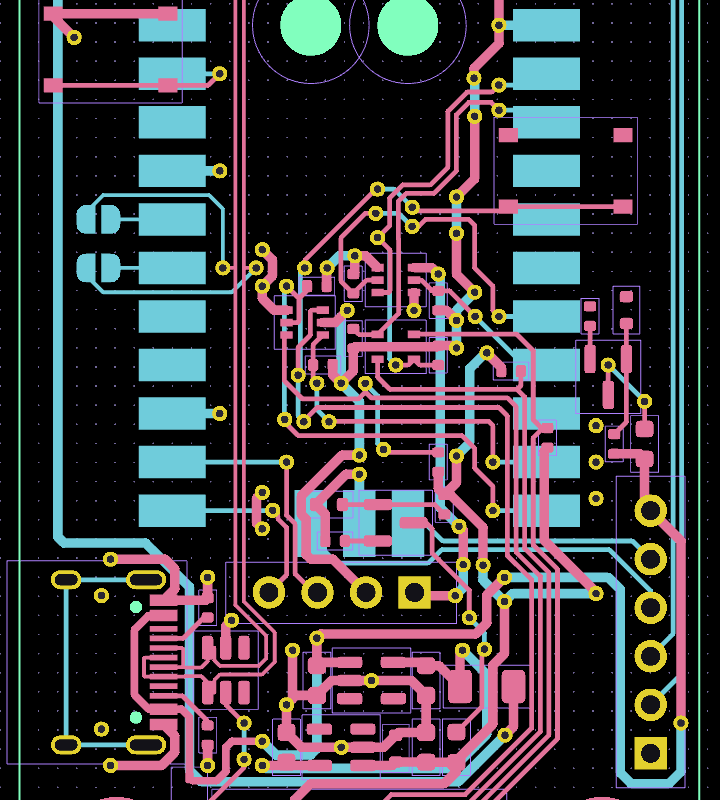
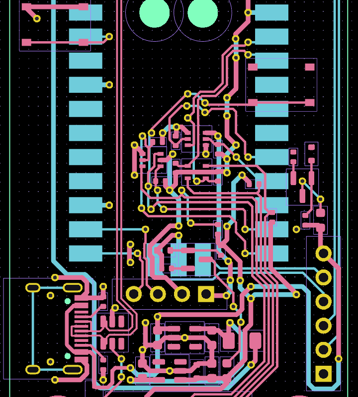
…and here’s how we made the pcb changes!