usb3sun rev A3, guaranteed to not hurt your eyes!
(unless you’re having a migraine or something)
usb3sun rev A1 added two led indicators that are run at 15mA, or 80% of the brightness of the nominal 20mA. since this was done passively with a resistor, that current and brightness only applies when the supply is exactly 5V. this was Way Too Fucking Bright.
usb3sun rev A2 reduced the current down to just 3mA or 10% brightness, again only when the supply is exactly 5V. this was Still Too Fucking Bright.
fed up with this, i decided i wanted to find the ideal brightness for this model of led before my next order. i had a couple of existing boards from rev A1 and rev A2, but i didn’t have the requisite Yet Another $30 Tool™ to replace 0402 resistors, and strictly speaking you can’t increase the value of a resistor by only adding things.
@bark pointed out that we can effectively increase the value by bridging a resistor in parallel with the load. the lower its value, the more current is stolen from the load.
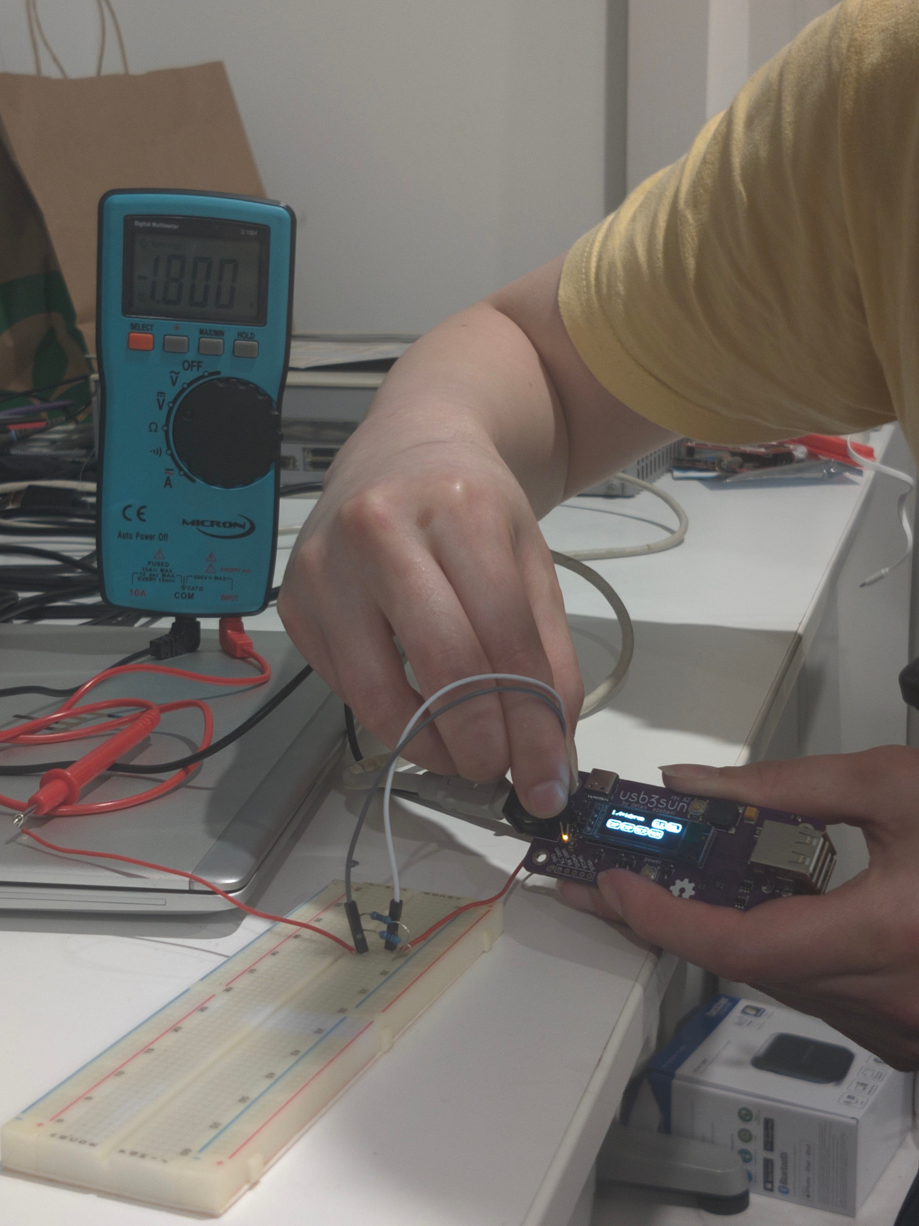
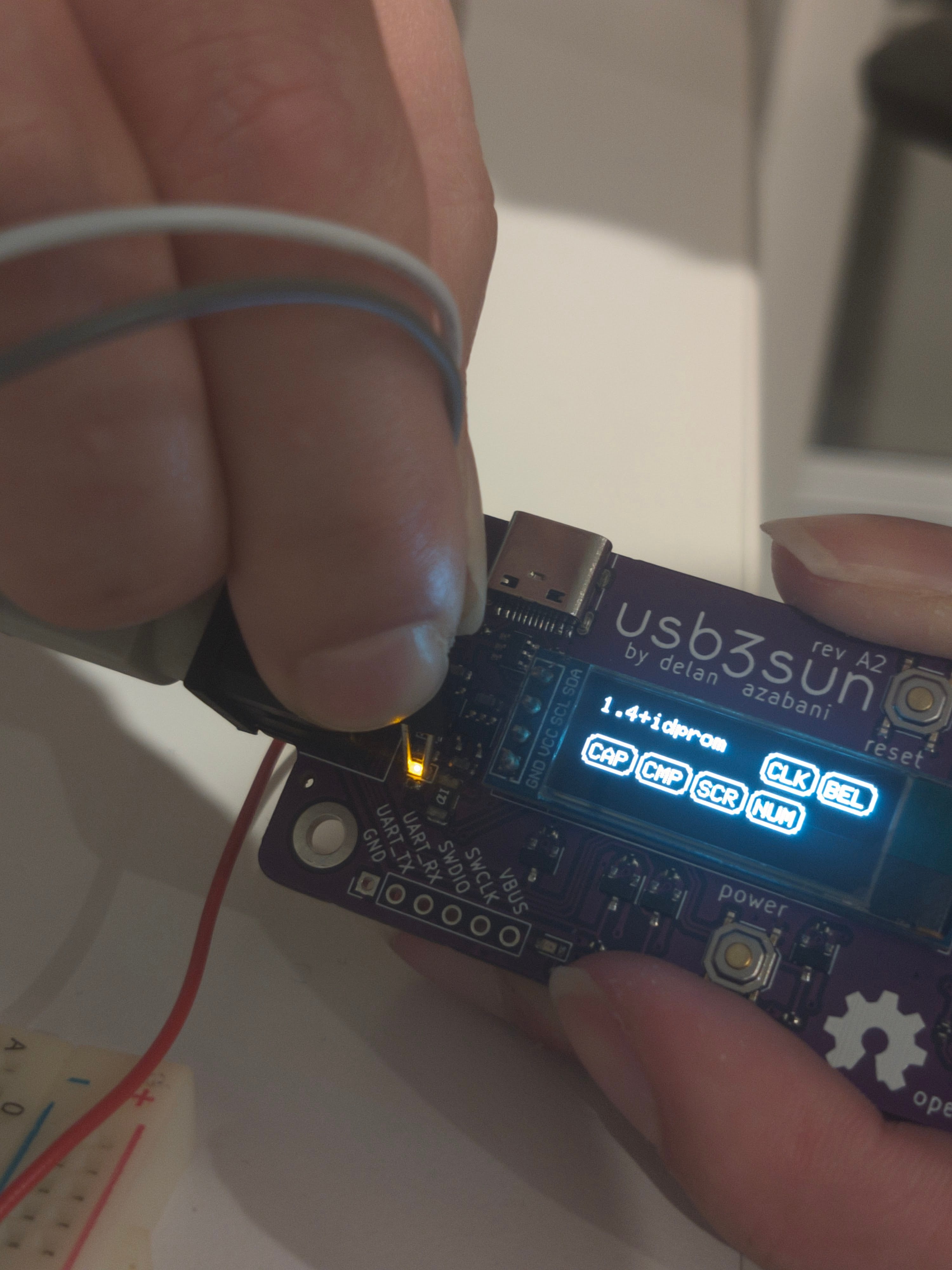
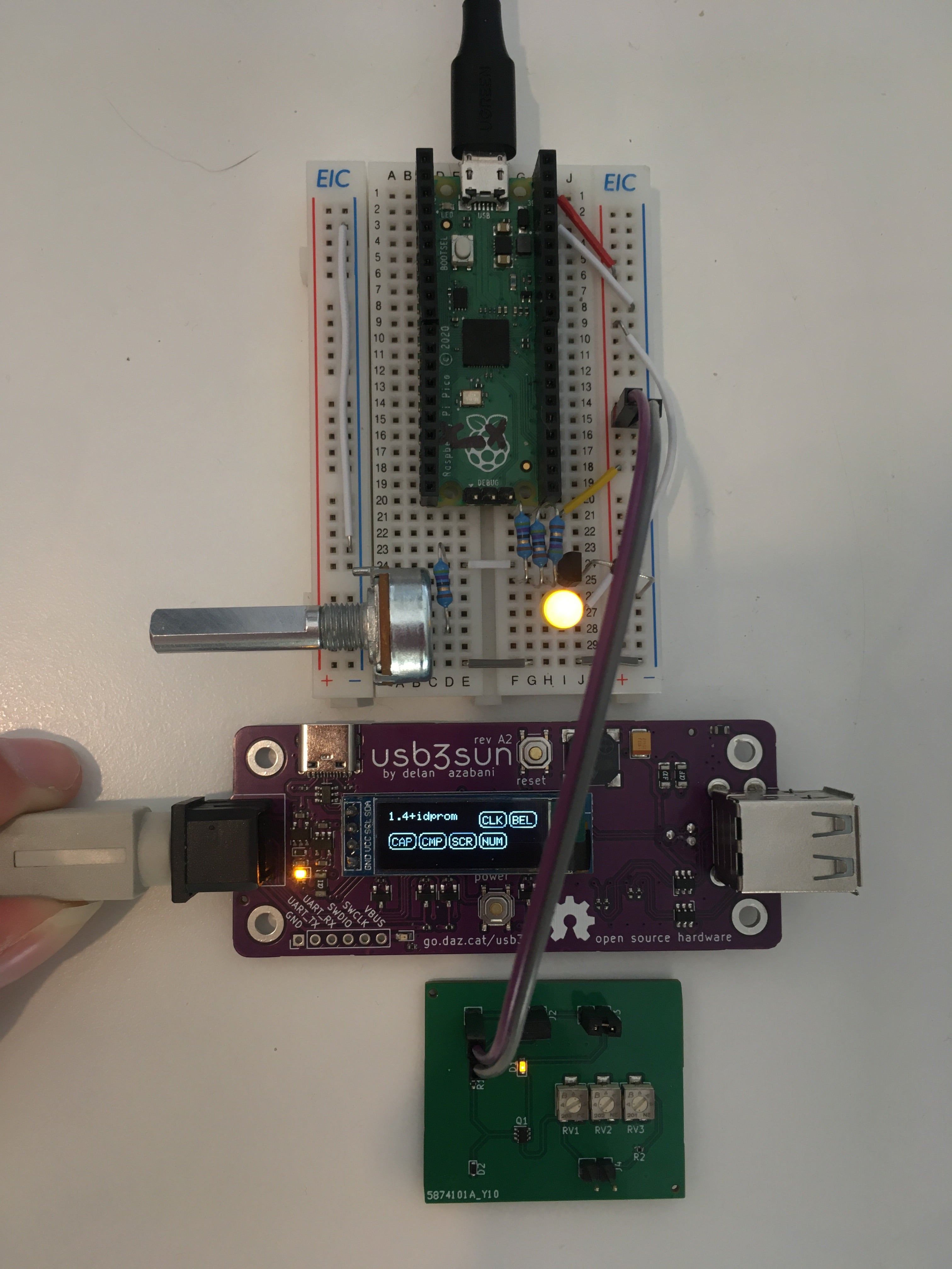
of the values i could be bothered trying with plain old resistors, i liked the brightness best when i bridged 670R across the load. this meant the led was only pulling 406µA (Vf = 1V843), equivalent to replacing the 1K resistor with 7K771!
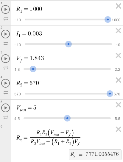
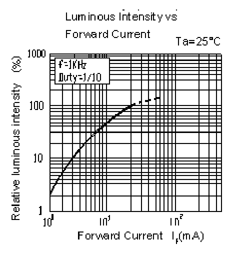
unfortunately, if we were to do that in rev A3, we would actually get anywhere between 367µA at 4V7 and 470µA at 5V5, and per the datasheet, the brightness over current curve gets Very Steep near 1mA. one could only imagine it gets Even Steeper below 1mA.
https://www.desmos.com/calculator/es3ybgxszd
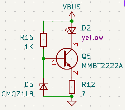
to put this problem to rest once and for all, i decided to upgrade each led indicator to use a zener diode current source, with the help of this post and this calculator. in short, it exploits the clamping behaviour of a zener diode to hold the base of an npn transistor at a constant voltage, which in turn maintains an almost constant current through the load. the gain (hFE) of the transistor doesn’t really matter as long as it’s reasonably high, though the behaviour is susceptible to interference via temperature.
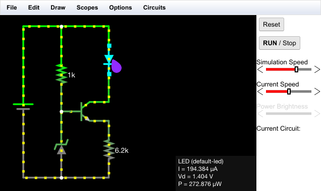
i built a test board to find the ideal brightness for this model of led, with the help of some pots, and i ended up with Re = 6K2 or so. running the numbers, that comes out to just under 200µA. i can’t even confirm this irl, because my multimeter doesn’t go that low.
was this really necessary for two led indicators? probably not. but fool me once, shame on you, fool me twice, uhh, you can’t get fooled again. i think. ask george dubya.