the cursed “usb” card reader
so we have this card reader that goes in a 3.5″ floppy bay.
but that’s unusual… it also has four usb 3.0 ports? i guess that would explain the pcie card, it must come with a usb host controller! it also has the usual usb 2.0 header for the card reader, which seems inelegant but i guess beats losing one of the ports.
that pcie card looks interesting though, let’s crack it open.
it looks like the cable connects to the board with a usb 3.0 header, which suggests the host controller is here, just like the front panel headers on your mainboard. look the silkscreen even reads D2+ D2− GND TX2+ TX2− GND RX2+ RX2− PWER!
but how is the board so small? on the other side, the silkscreen reads ID D1+ D1− GND TX1+ TX1− GND RX1+ RX1− PWER, which is again the usb 3.0 header pinout, but there’s no controller in sight. what gives?
well it turns out the silkscreen was a lie. we’re running pcie over a usb cable, and the controller actually lives in the main unit. abusing usb 3.0 cables like this is more common than you might think!
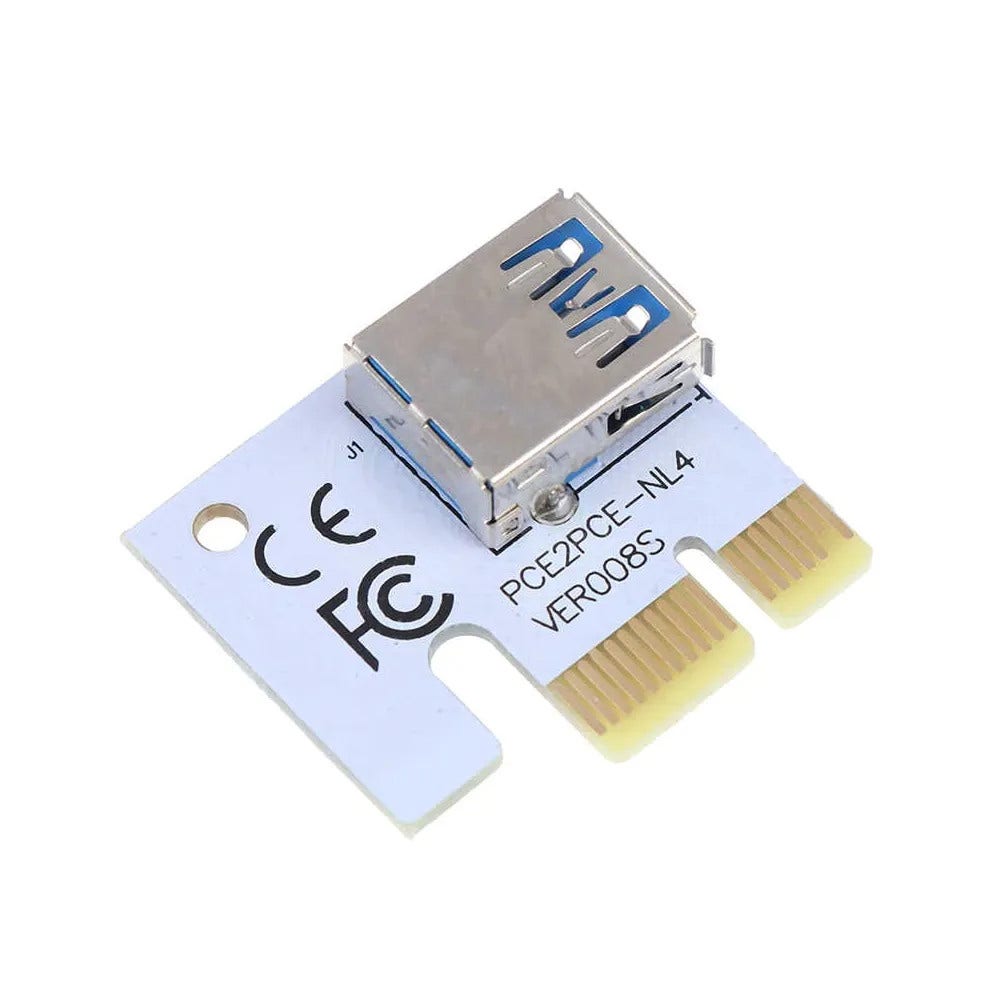
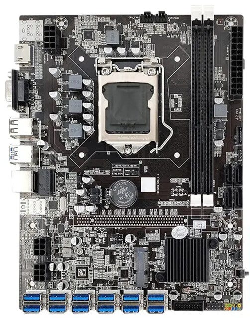
for example, this riser converts an ordinary pcie slot to a “usb port”, while this mainboard has a dozen “usb ports” along the bottom, which are actually pcie x1 ports. this is often used by the cryptocurrency mining “industry”.


oh and in case that wasn’t cursed enough…
yep. fun fact: it uses the USB ground pin as a signal pin, and USB shield as ground